https://www.rcgroups.com/forums/showthread.php?2979631-AkaModell-Munich-new-HLG-project-2017-2018
http://www.rc-network.de/forum/showthread.php/658162-AkaModell-M%C3%BCnchen-%E2%80%93-unser-neues-F3K-Projekt-2017-2018
1 Introduction
Hi everybody! In this thread we want to introduce our new F3K project! Right now, it is work in progress, but a lot has already happened and we like to share our progress with you. We are still looking for a name for the aircraft, maybe you have some great ideas?
1.1 Who we are
We are the AkaModell from Munich, a group of students from Munich who work on RC aircraft and drone projects. We take part in student competitions like the Air Cargo Challenge, where we finished 2nd out of 28 teams in the 2017 edition of the Air Cargo Challenge. We do all the design and build ourselves and we usually work with MATLAB, CATIA V5, XFLR5, XFOIL, MSES/MSIS.
Since 2002, the AkaModell Munich has developed some F3K models. However, they were hardly used at contests, as our pilots rather focused on F5D pylon racing in the past. The F5D model “Batleth” was quite successful in the mid to end 2000’s. Some of the HLG designs were also experimental and not meant to enter international contests. Our HLG models are “Genius” (2002), “Climax” (2004), “Bachelor” (2012).
1.2 Motivation for a new project
Five years have passed since our last HLG design and technology made huge progress. Light and strong NCFs, 1s LiPo setups, super strong mini servos and full foam core technology have revolutionized F3K. None of our old designs can really profit from these advances – so it’s time to make a new airplane!
1.3 Goals
Of course, the build shall be according to the F3K FAI regulations. We have learned a lot from the past designs and we can learn even more from current competition models. We want to create a high-performance model, which is easy to build at the same time. The “Bachelor” had many difficult elements in the build and a lot could go wrong. This shall not happen anymore. We want to apply all modern building techniques like full Rohacell core to get an airplane at about 250g AUW. As our cnc-milling machine is only 800mm long, we decided to make a two-piece wing design, like the two-piece Snipe or Vibe. The airplane is not meant to attack the leading F3K models in competition, but we expect high performance from our design, so taking part in a competition should be fine.
1.4 Who I am
I am Alex and kind of the project leader. I just graduated my Master studies at TUM with my thesis about automated low Reynolds number slotted airfoil design and optimization with MSES. Right now it is time for me to pass some know-how to our newer members and this is my personal motivation for this project. Besides the fact that I will get a nice HLG ?.
2 New design
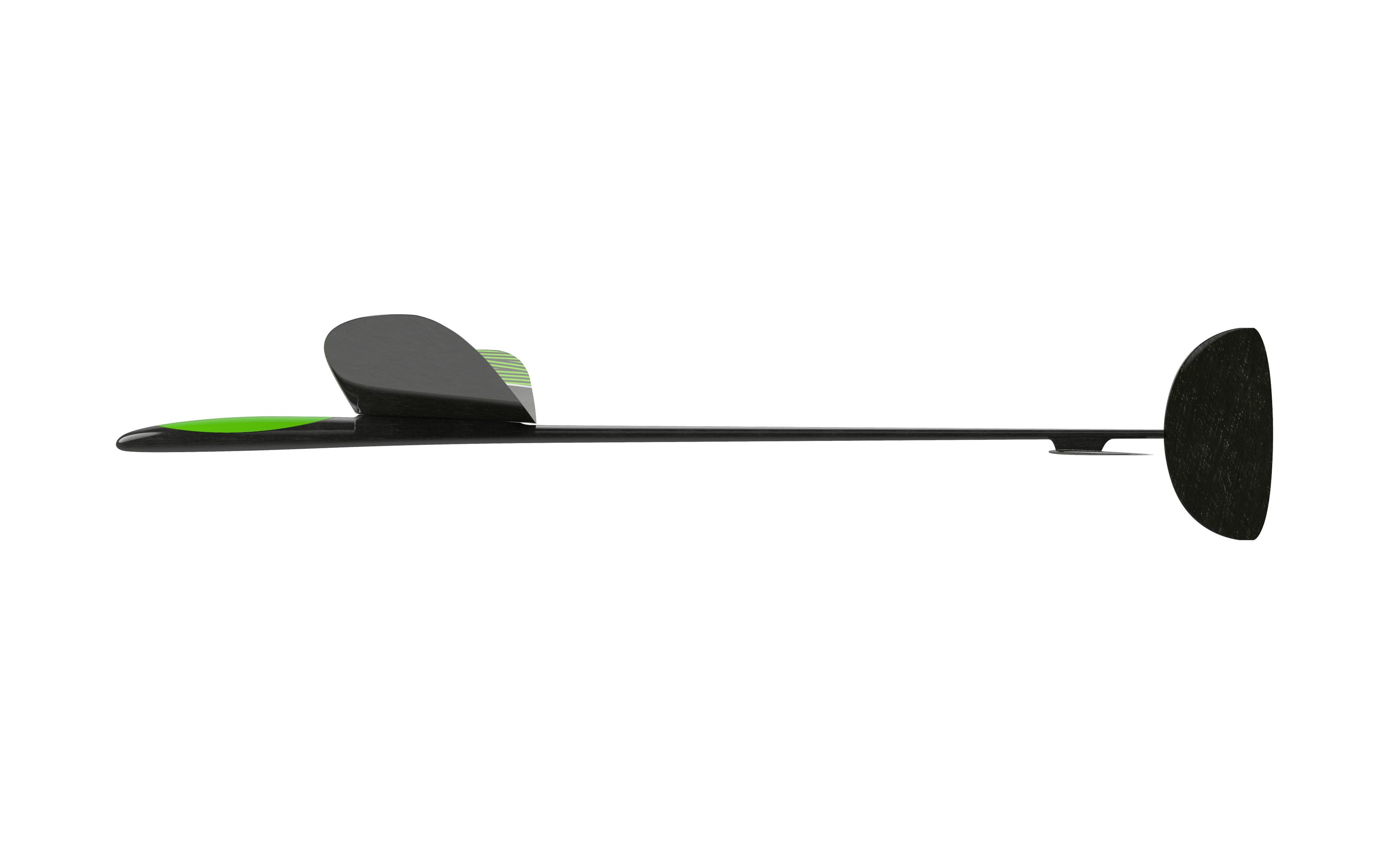
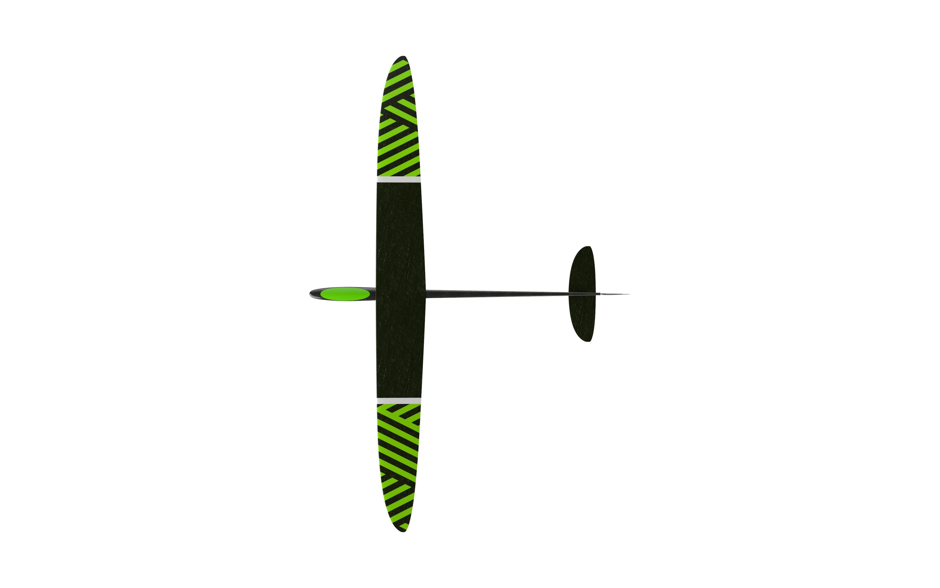
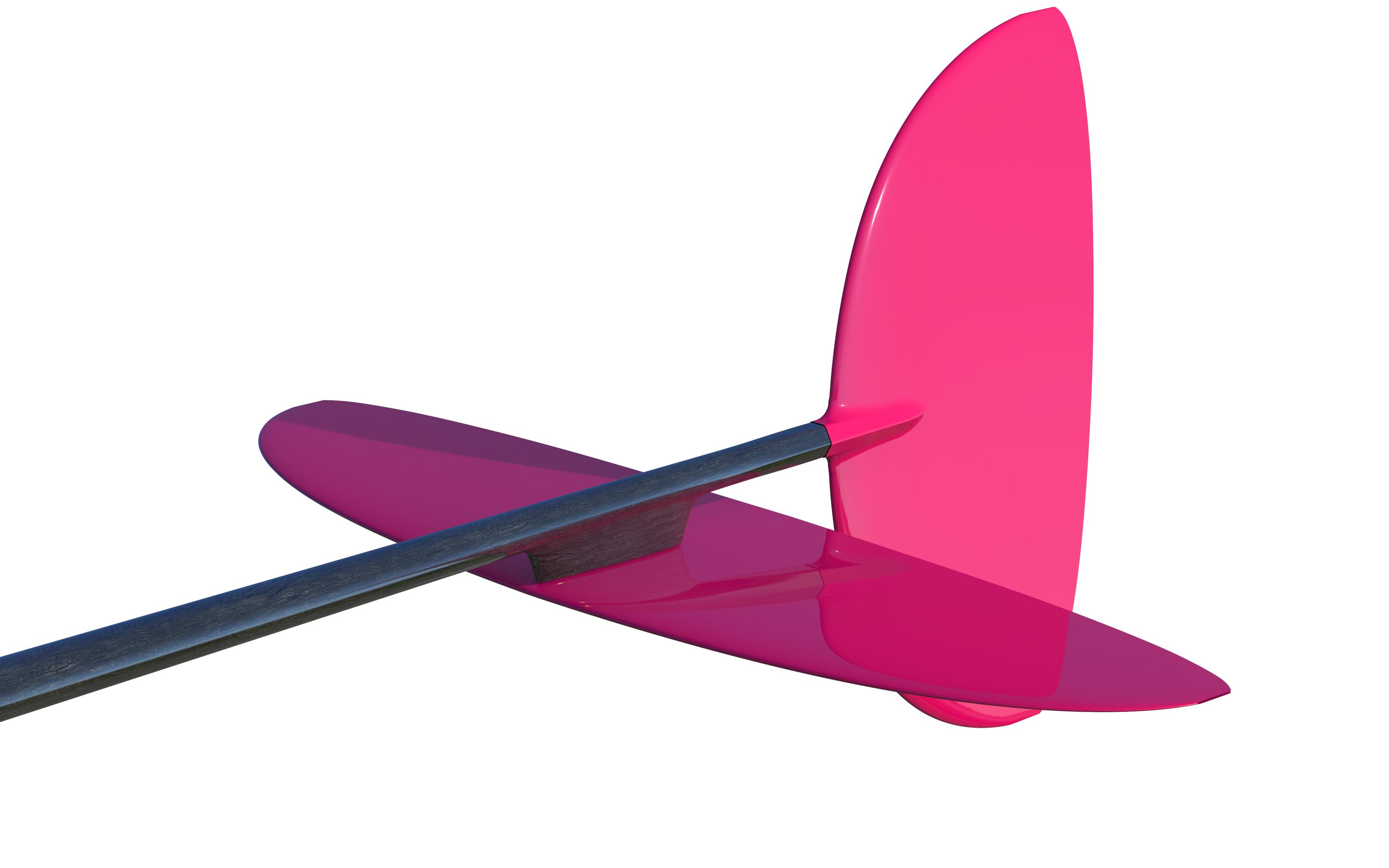
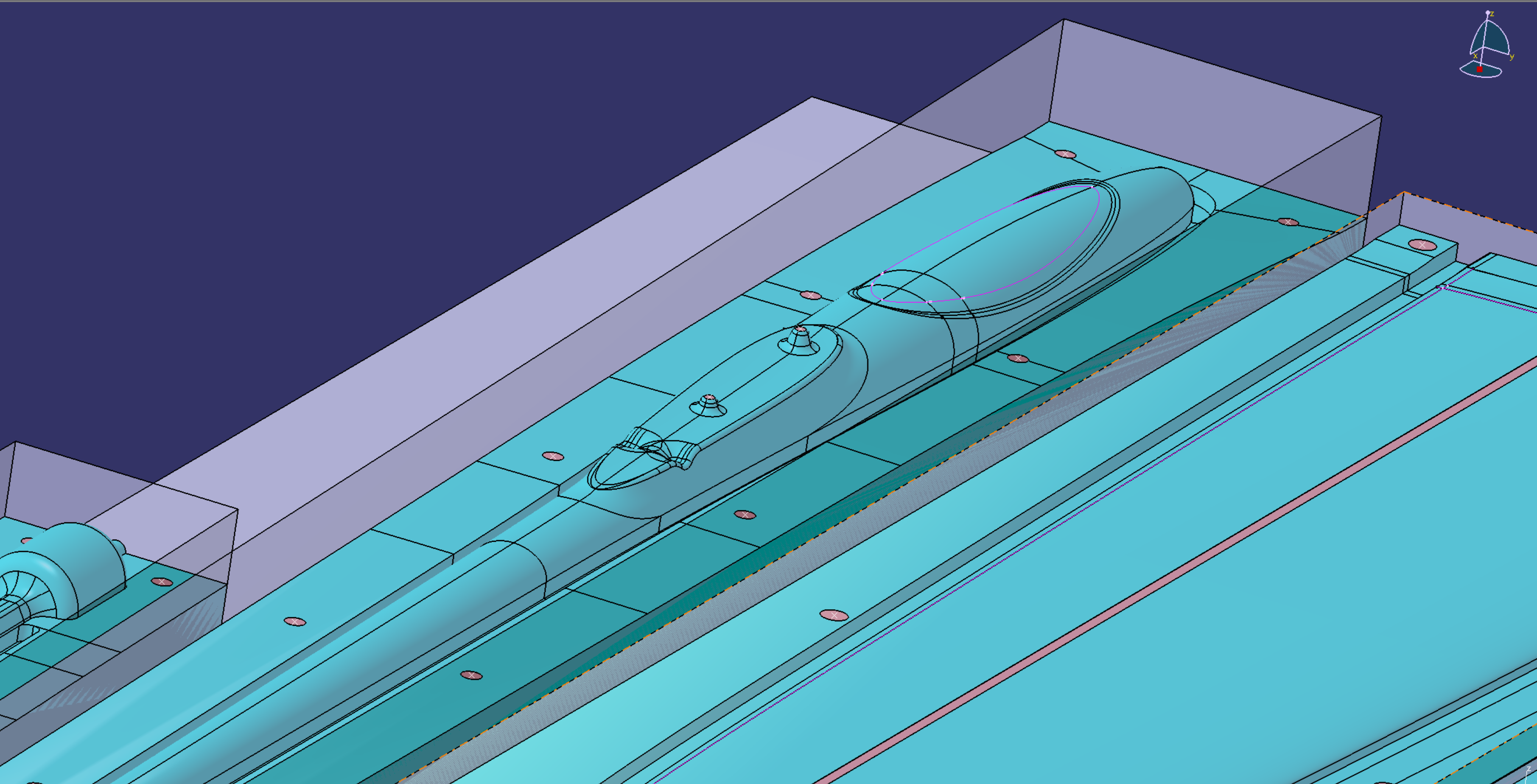
Before getting into details, find a sneak peek in the images! The renderings are an excerpt of our WIP and many details are not realized in CAD yet or may change. But it is enough to show what we are up for.

__________________________
2.1 Short history
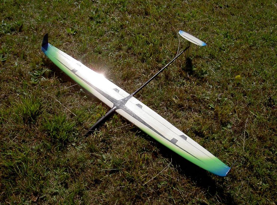
Here some images: The fleet with the three planes are the “Genius” model, with different empennage configurations. Back at that time it was common to build the wing shell sandwich from glass fiber with balsa wood core.
The blue/green single airplane with the large winglets is our “Climax”. It is a rather experimental configuration with T-tail and four-flap-wing. The winglets serve as throwing peg here. As far as I know was thermaling excellent, but the throwing heights were never competitive enough. The large winglets generated too much drag during launch. And the winglet trailing edge was rather sharp, which is not good for the thrower’s fingers.
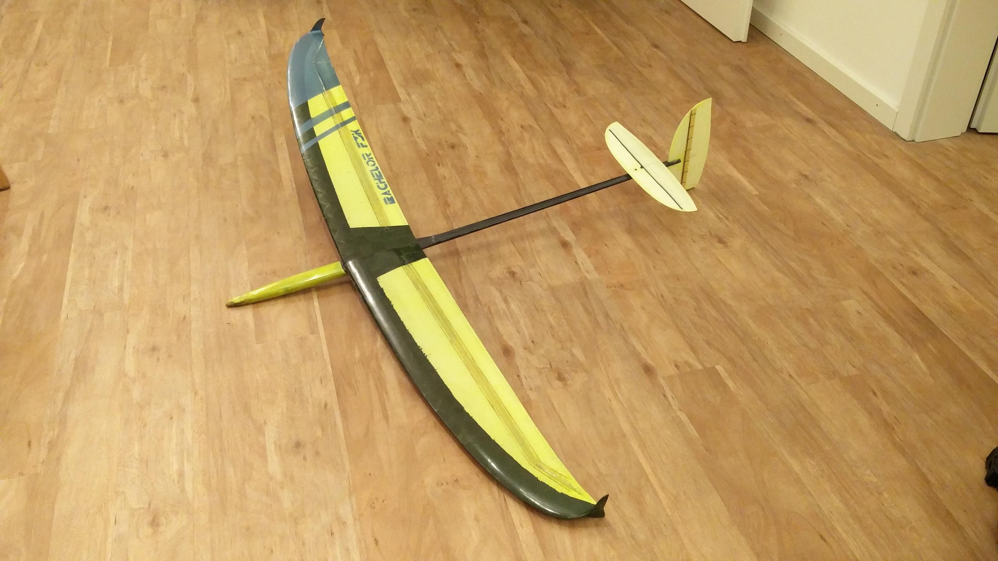
With the “Bachelor” (yellow) we hoped to overcome the drag issue by shrinking the winglet to the size of a throwing peg. This is the only design I can answer all kinds of questions as I worked on this airplane at the beginning of my studies. We reused the climax airfoils with about 8.5% thickness at the wing root to 6.5% thickness at the tip. Like the “Climax”, the “Bachelor” is great for flying in thermals, but it cannot keep up with modern DLG’s because of one simple fact: The airplane is too heavy. With about 300 g AUW, you can hardly beat modern 230 g designs in sink rate and agility. The wing is built in shell construction with 1 mm Rohacell. To save some money and weight, we made most of the planes with a 60 g/m² IMS spread-tow D-box and the rest with 27 g/m² g glass fiber. The aileron servos are in the wing. The yellow wing in the picture is 176 g. The tails are full core, a good set has about 15 g. So, overall the build is rather heavy compared to modern full core designs.
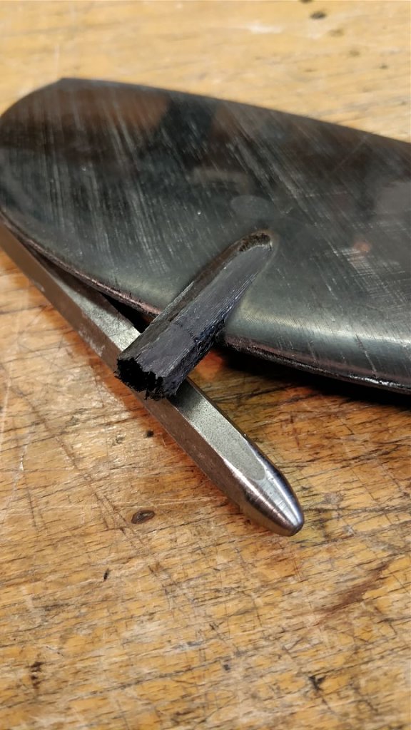
The molded winglet/throwing peg design adds a lot of weight at the wing tip, resulting in high momentum around the height axis. The best launches were about 48 m. The “Bachelor” fuselage is hard to build and it needs some training to make a nice fuselage. A lot of sharp edges! But there is one thing that we really like about the “Bachelor” fuselage: We inserted a 1.5 mm steel wire between the carbon layers in the tail boom. After curing, we removed the steel wires and we were left with integrated pushrod channels for 1 mm carbon rods. I did a lot of destructive testing with different layups, 0/90 spread tow finally worked out to avoid some severe buckling at the region right behind the trailing edge. Despite the little problems with the build, the “Bachelor” was very popular among our new members and some guys built one. Nowadays, we use it for launch training in the spare time between lectures and hang gliding.

________________________________
2.2 Design ideas
We assembled our new concept learning from our old builds and numerous other competition DLGs. Some of our basic thoughts:
– full foam core wings and tails, cnc-milled cores and negative production molds. To achieve a high-quality build, this is the only way to go. Working with positive construction techniques requires experience and training and the aerodynamic quality of the leading edge is rather poor.
– We want a two-piece wing because of our milling machine size limitation. We know it will add some weight and complexity, but we are convinced it is more practical in our case. With the two-piece design in mind right from the beginning, we can design molds with specialized wing root geometry.
– monocoque fuselage with small lid-type canopy. The “Bachelor” had a slip-over canopy (sorry, I am not sure how it is called in English…) and it is an extra part to build, heavier etc…
– As some our students cannot afford something like super small and light MKS or KST servos, we need a little more space in the front fuselage. Also, many guys of us want to fly with a FrSky vario for training. 1s or 2s LiPo batteries should be possible.
– All servos shall be in the fuselage. It is simpler to replace a broken wing or upgrade from first glass fiber (tests) to expensive and final carbon fiber layup wings. Also, wings for strong and light conditions could be swapped quite easily that way.
– The fuselage design shall avoid sharp edges. This means we renounce all transitions from fuselage to the wing that require roving fillings, microballoons or carbon powder filling. Usually, fillets are heavy and increase the risk of having cavities. Also, the wing shall not have fairings to the fuselage. All in favor of weight and fiber bending radii. One day we want try to use out-of-autoclave prepreg, but it’s hard to get some in the right material. Perhaps someone here has good connections?
– We really like the way the ailerons are connected to the servos in the Vortex 3. We try to implement this solution for our design. I think we will 3D-print the servo frame from carbon reinforced filament… If this does not work, we will fall back on the solution the Snipe 2 offers.
– Although we like the integrated pushrods in the fuselage tail boom of the “Bachelor”, we think that spring loaded tails with string connection to the servos are more lightweight. The elevator shall sit under the fuselage, so pulling the string is pulling the elevator.
– The throwing peg will be a classical solution, no winglets this time! Right now, we favorize the push-through type (like Steigeisen, FW5, Stream NXT…). But it is not fixed yet. Maybe you have some feedback from your DLGs to share and convince us of the best solution!
– We do not want to use gluing templates, so everything should be molded directly.
– The elevator will be screwed onto a little pylon, so it can be detached for transport. We plan a hexagonal tail boom ending and we want to insert an Allen key space holder while building the fin. Like this, we get a fitting between fin and tail boom. Then we can slide on the fin and it should align with the boom correctly. Maybe like this it is also possible just to fix the fin with tape and make it detachable. I will show some pictures as soon as it is constructed in CAD.
– Some thoughts on aerodynamics: The airfoils tend to be very thin (more later. We have our own, new airfoils…). Flaps nowadays are already set in cruise flight mode to 1° or 2° to get a little more camber. The flap setting shall not obstruct the lift distribution shape. So, the airfoils on the whole wing will be aligned to have the flap at 70% chord. More on our wing layout later, it is the result of a custom programmed optimization tool.
This text will be supplemented by pictures once I introduce the detail solutions step by step. I hope our ideas are clear to understand. Please do not hesitate to ask if I formulated something unclear!
___________________________
2.3 Aerodynamics
Let’s talk about how we got to our design. The glider wing geometry and airfoils are result of a multi-objective optimization tool. I will describe the overall process and then go into some details. Before starting, I want to remark that I try to explain the design process as easy as possible. Don’t hesitate to ask if there are questions. I have worked on airfoil and aircraft optimization now for longer and maybe I forget to explain something, because it’s clear to me.
2.3.1 Optimization workflow
First, the tool creates an airplane geometry from input parameters. Input parameters are for example wing surface size, taper ratio, flap deflections, wing twist, airfoil geometry, wing sweep… and some more. This makes about 12 parameters, which can generate completely different airplane geometries. High aspect ratio, wings with strong taper, almost rectangular wings, thick airfoils, thin airfoils…everything is possible!
Second, the aircraft design is evaluated in respect to its aerodynamic performance. How good is the design? This can be measured on certain criteria, which represent the demands of a “good” airplane design. For example, a high lift to drag ratio is desired for almost every glider. With a high lift to drag ratio, a glider can cover more distance from an initial altitude. This would make up one optimization goal. Those goals are also referred by the term “objectives”. Another objective would be a very low sink rate for a glider, which is applied for flying in thermals. In dead air, the glider with the least sink rate will hit the ground last and fly the longest time (from the same initial altitude). The other way around, it can climb faster in thermals. For F3K, the launch is also crucial. The aircraft shall have little aerodynamic drag at high airspeeds. An aircraft with higher drag will not reach the same altitude as one with less drag.
There are more possible objectives, which can reflect the handling characteristics. Such as stall behavior, where the local lift coefficient distribution is evaluated. Or all-round properties of the airplane design could be investigated, to create an airplane that flies well in a large range of airspeed.
To sum it up: We want an airplane with high lift-to drag ratio, low sink rate, low drag at high speed and nice handling characteristics. The design tool tries to find airplane geometry, which fulfils this in the best way.
The three flight states (launch/cruise/thermal) should be well known to most of you. And how do you encounter these different flight modes? With flap settings! By setting your flaperons, you can control the wing camber and adapt your wing to the current situation. So, the optimization tool also takes care of finding the optimal flap settings. Airplane and airfoil geometry and flaps are optimized at the same time to create a perfect match!
Back to the design process. The tool makes a design from parameters and then evaluates it. Actually, this is done at once for a bunch of aircrafts, about 20 to 100 in one step. With the results of the evaluation, the optimization algorithm adapts the input parameters. Some of the modified parameters will lead to better aircraft designs. And this is repeated over and over. By the number of iterations, the airplanes get better and better. In the beginning, the design parameters are completely random, and many aircraft are just crap. At the end, we get a set of high-performance wing designs.
2.3.2 Tools
All is wrapped into a multi-objective optimization algorithm. The general goal of an optimization algorithm is to find a set of optimal parameters for a minimization (or maximization) problem. The optimization algorithm I use belongs to the class of metaheuristic algorithms. It can handle non-linear, mixed discrete and non-discrete design spaces and uses a Pareto-non-dominated ranking to evaluate the objective cost.
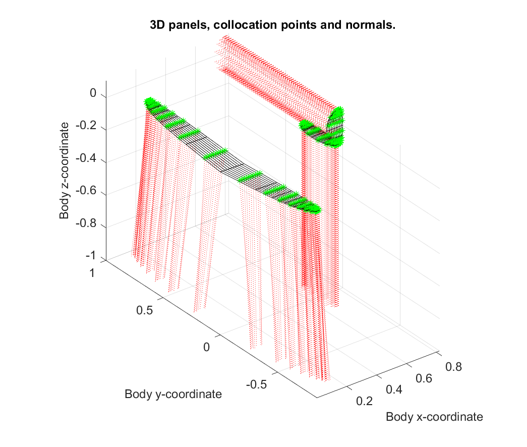
The aerodynamic performance calculation is a modified and debugged version of “Tornado Vortex”, a MATLAB implementation of a vortex lattice method. It’s kind of XFLR5, but I can interface it with external MATLAB scripts. I replaced the buggy viscous drag calculation by script interfacing XFOIL (or MSES). Like this, we obtain all aerodynamic coefficients, wing loading etc. and then we can calculate some performance indicators like lift to drag ratio for instance. Another element that I added is a script which translates the input parameters of the optimizer into an airplane geometry description.
XFOIL should be the well-known to anybody, who ever dealt with airfoil aerodynamics. At this point, I don’t want to lose too many words on it, except that it is used for 2d airfoil polar calculation. MSES (by Mark Drela) is an alternative to XFOIL. MSES can handle multi-element airfoils and compute transonic flow states. For F3K transonic computation is hardly necessary 😉 but as far as I know dynamic soaring designs like the Kinetic used MSES in their design process. We used MSES for our slotted wing design for the Air Cargo Challenge 2017.
At the end of the optimization run, I transfer the final solutions to XFLR5 to evaluate them manually and check the results myself. This gives a good understanding of the compromises you must make as an aircraft designer.
2.3.3 The Reynolds number problem
But why this effort? In lecture you learn that the best wing is elliptical? So why not taking an elliptic wing depth distribution and just be satisfied? At small Reynolds numbers, viscous drag is an important influence factor. The Reynolds number depends on the local wing depth. Small wing depths (and small Reynolds numbers) lead to higher airfoil drag. So, increasing the wing depth at the outer wing helps. However, the best lift distribution of a wing is still (close to) the elliptic shape and high aspect ratio wings have higher performance. In F3K, the wing span is fixed, so this is not a big deal. To find the best balance of viscous drag and an efficient lift distribution, there are still many parameters left to tune. And not only for one flight condition, but at least three (launch/cruise/thermal) including airfoil choice and flap settings. Even for experienced human aircraft designers, this is a challenging task. For example: The automated wing optimization can easily calculate 2000 aircraft designs at 3 operation points with 10 individual airfoils on a wing. Which would make 2000 x 3 x 10 = 60k executions of XFOIL in one optimization run. This is far beyond human capability.
2.3.4 Results
After reading all this, you maybe expect a revolutionary design which blows off the existing F3K contest models. Well, this is not the case. On the one hand our wing does not look totally different than any current F3K contest wing. On the other hand, we obtained this shape not by copying others, but by a scientific approach to an optimization problem. There is also not “the best” design in the world, there will always be airplanes which are rather floaters and others for fast flying and windy conditions.
There are still some things that I could learn from working with the automated optimization:
– The optimizer would prefer wings with high aspect ratio and small wing areas. Surfaces of 15 dm² however would have a high wing loading. This leads to airplanes with little CL reserve and high flight speeds. Bad handling qualities and a very delicate wing structure are not, what we pilots wish to have.
– Thin airfoils combined with flaperon can give more performance. The airplane will require snapflap mixers and an attentive pilot.
– Current F3K airfoils (Zonev2, Ultima, …) are very close to the airfoils we obtained from our calculations. There is hardly any room for improvement.
– Optimizing an aircraft to certain handling characteristics and a high range of flight speeds is also possible with an optimization algorithm. Then, peak performance is sacrificed to obtain an aircraft which still flies well in gusts and forgives bad piloting.
For today, that’s it with the aircraft design process. Theory is not everything and that’s why we now need to go on making molds and test, if our calculations work out.
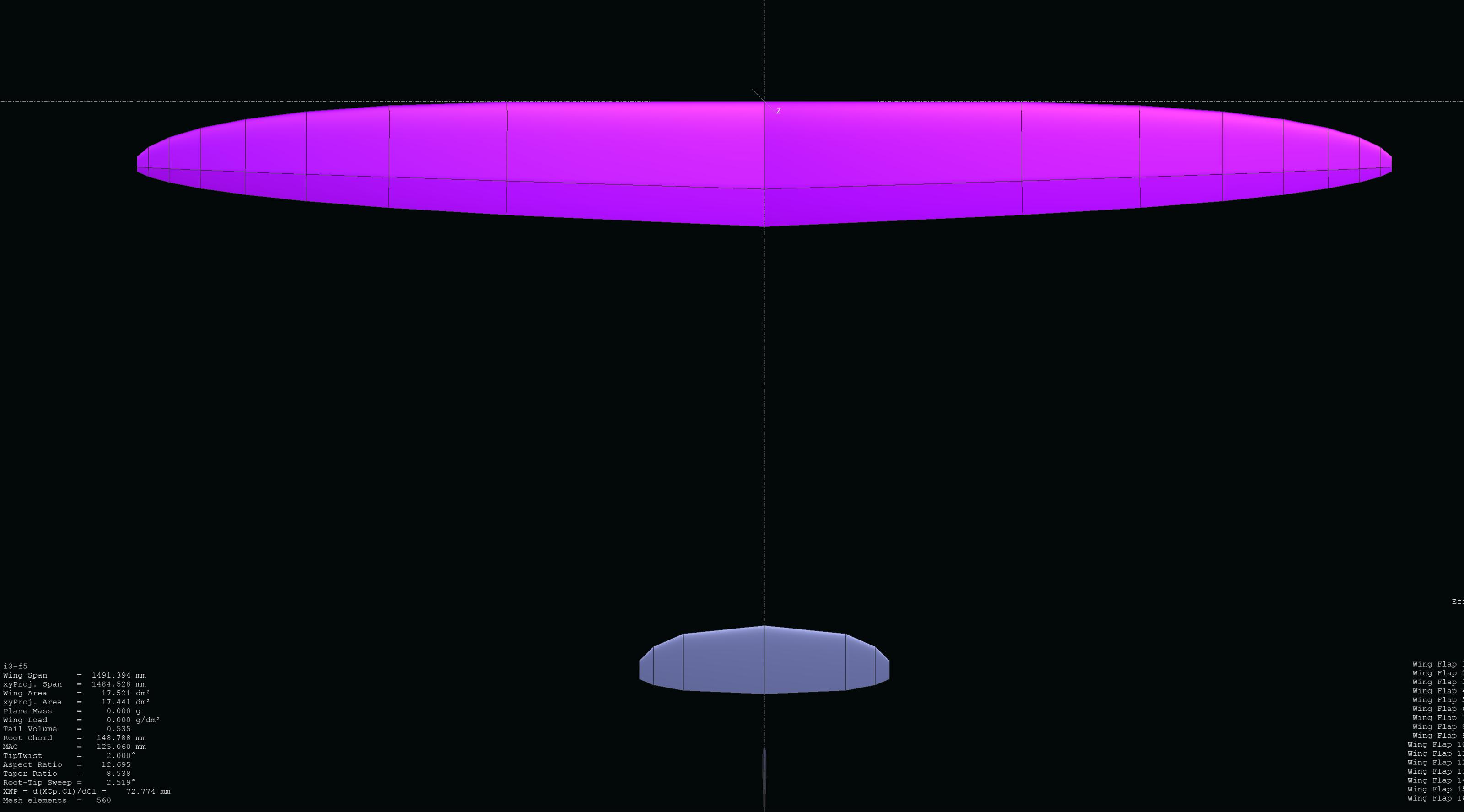
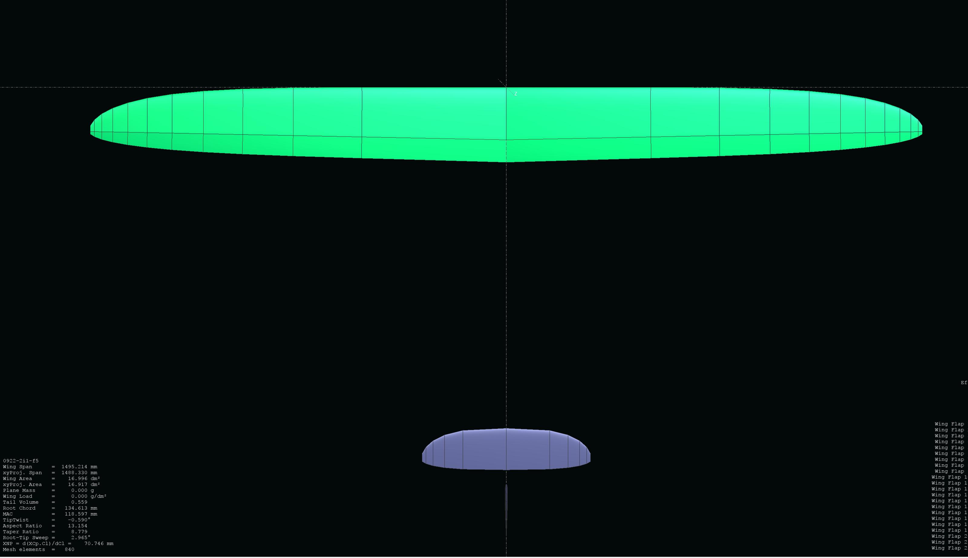
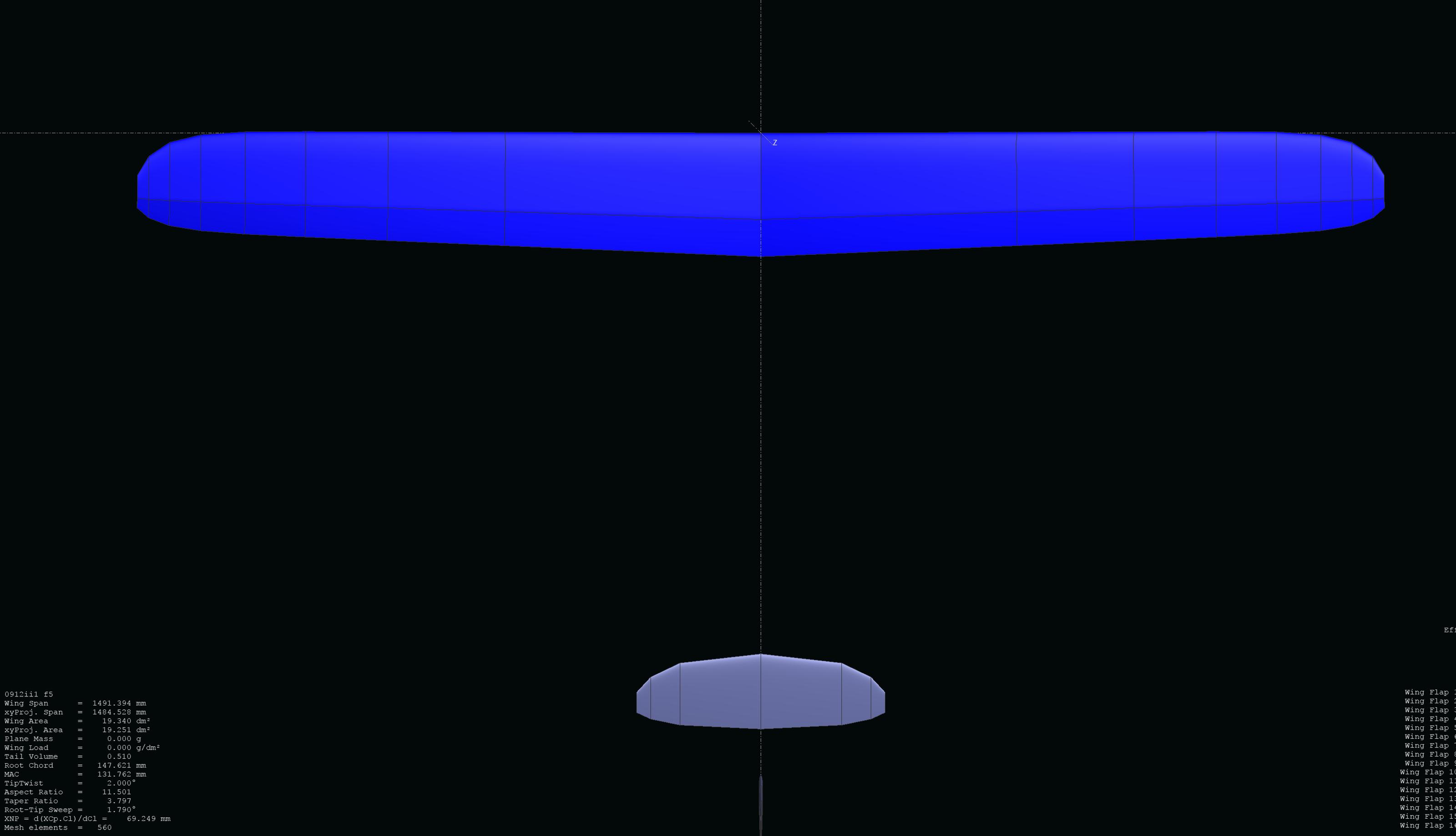
In the attachments, I put some images of Tornado Vortex and some examples for wing geometries from XFLR5.
Again, if you have questions feel free to ask! I am also looking forward to feedback from the experienced aircraft designers here in this thread.
I always have to prepare the posts a little bit, so it takes me some days to collect the content and write it down.


_______________________________
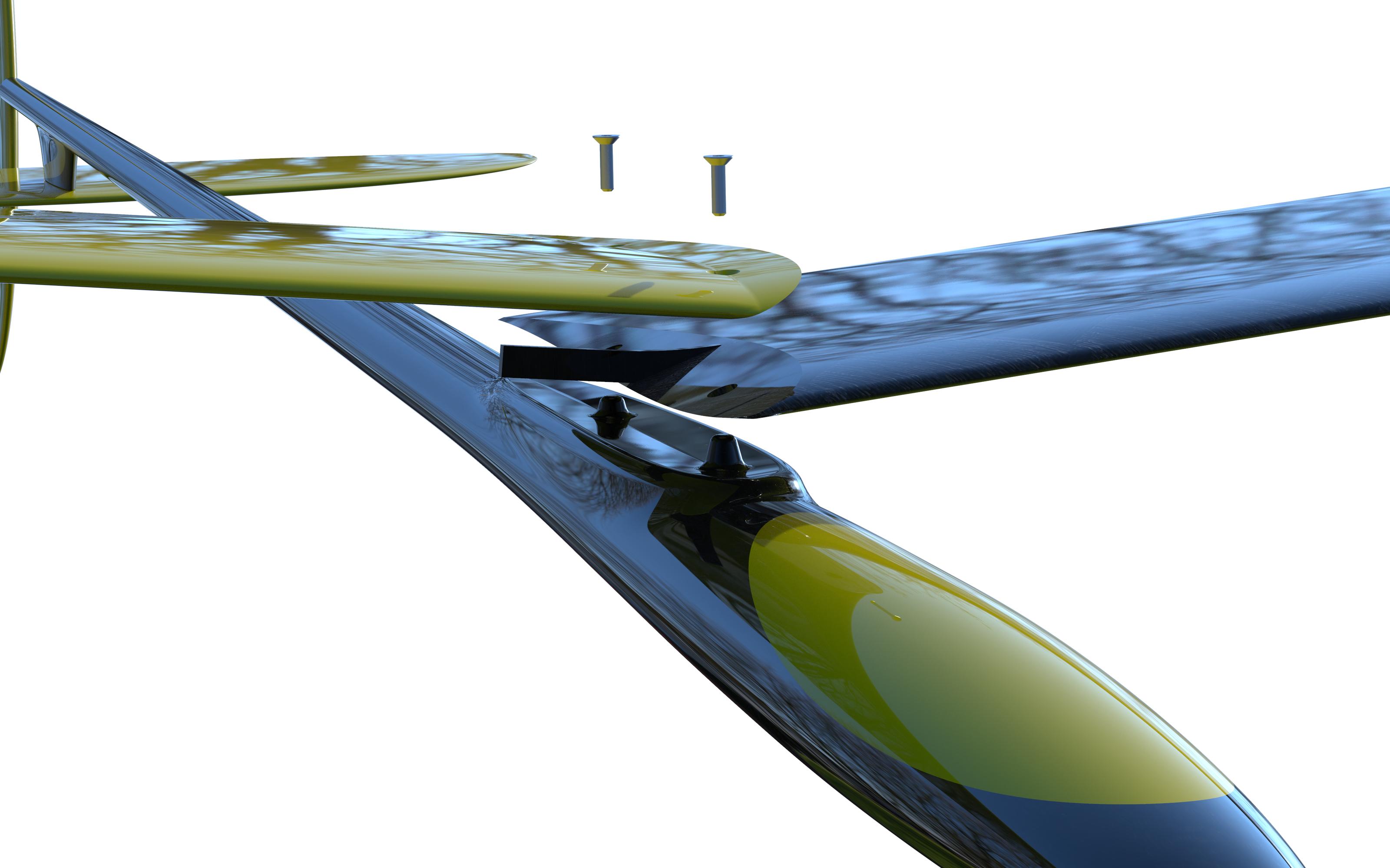
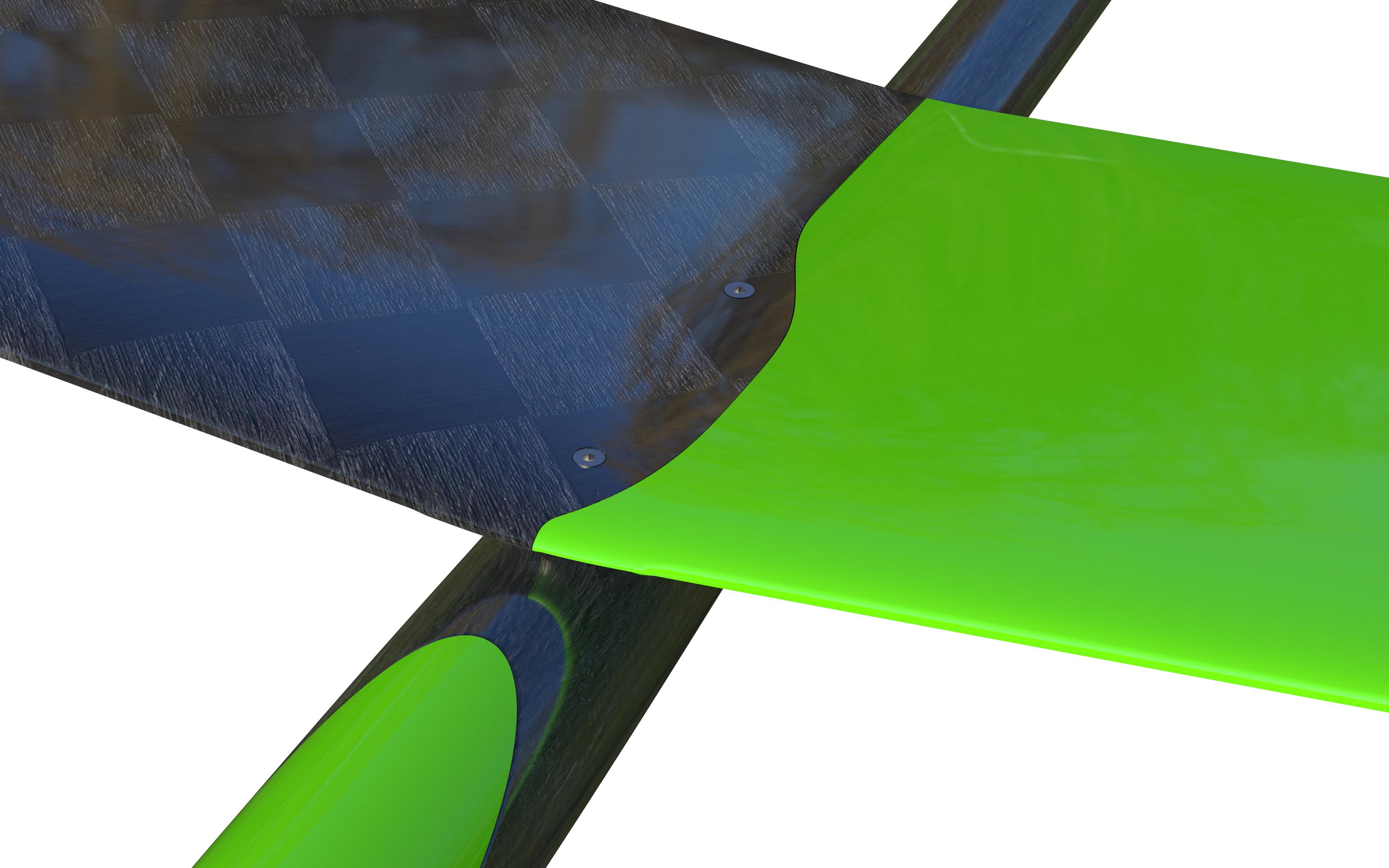
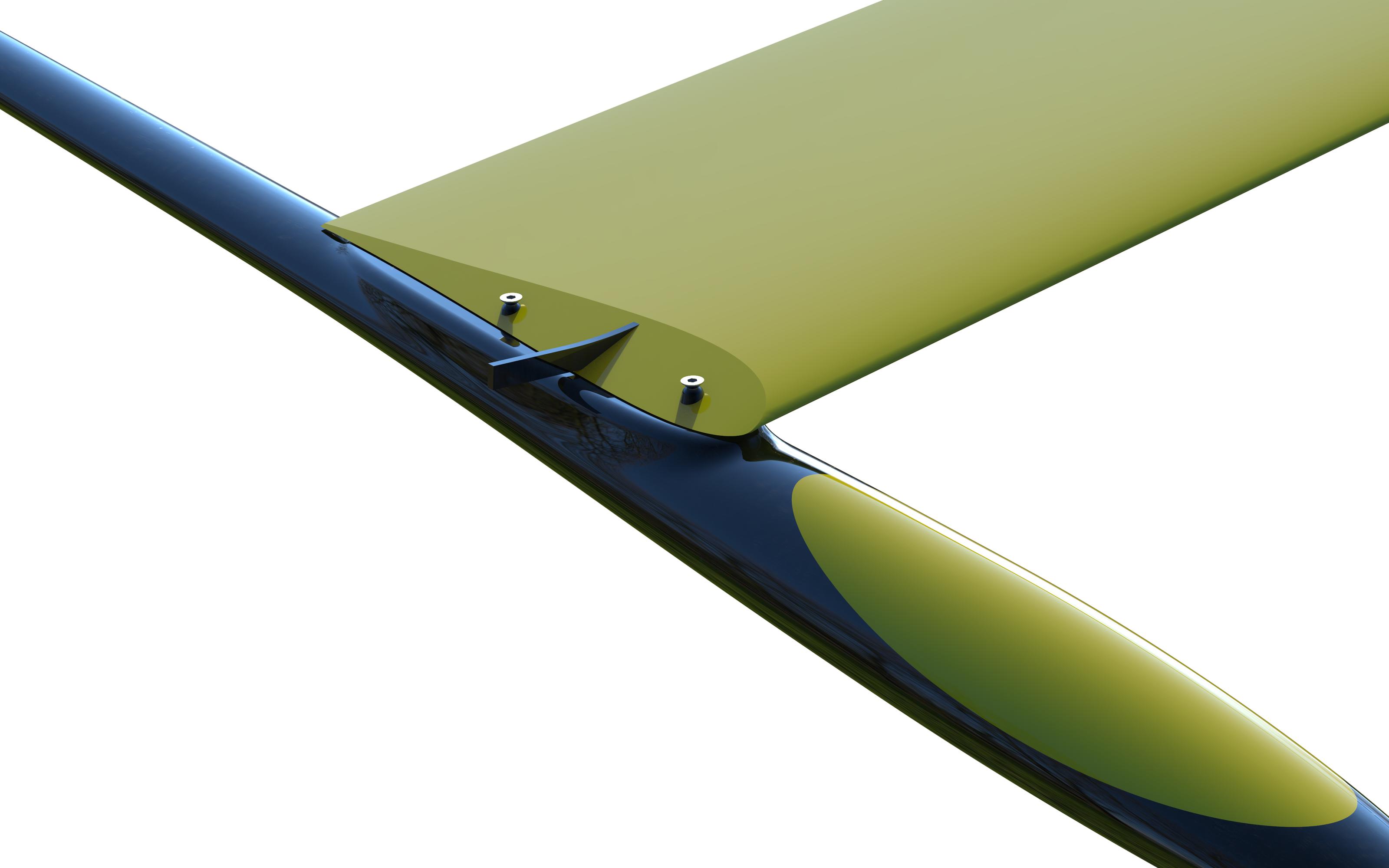
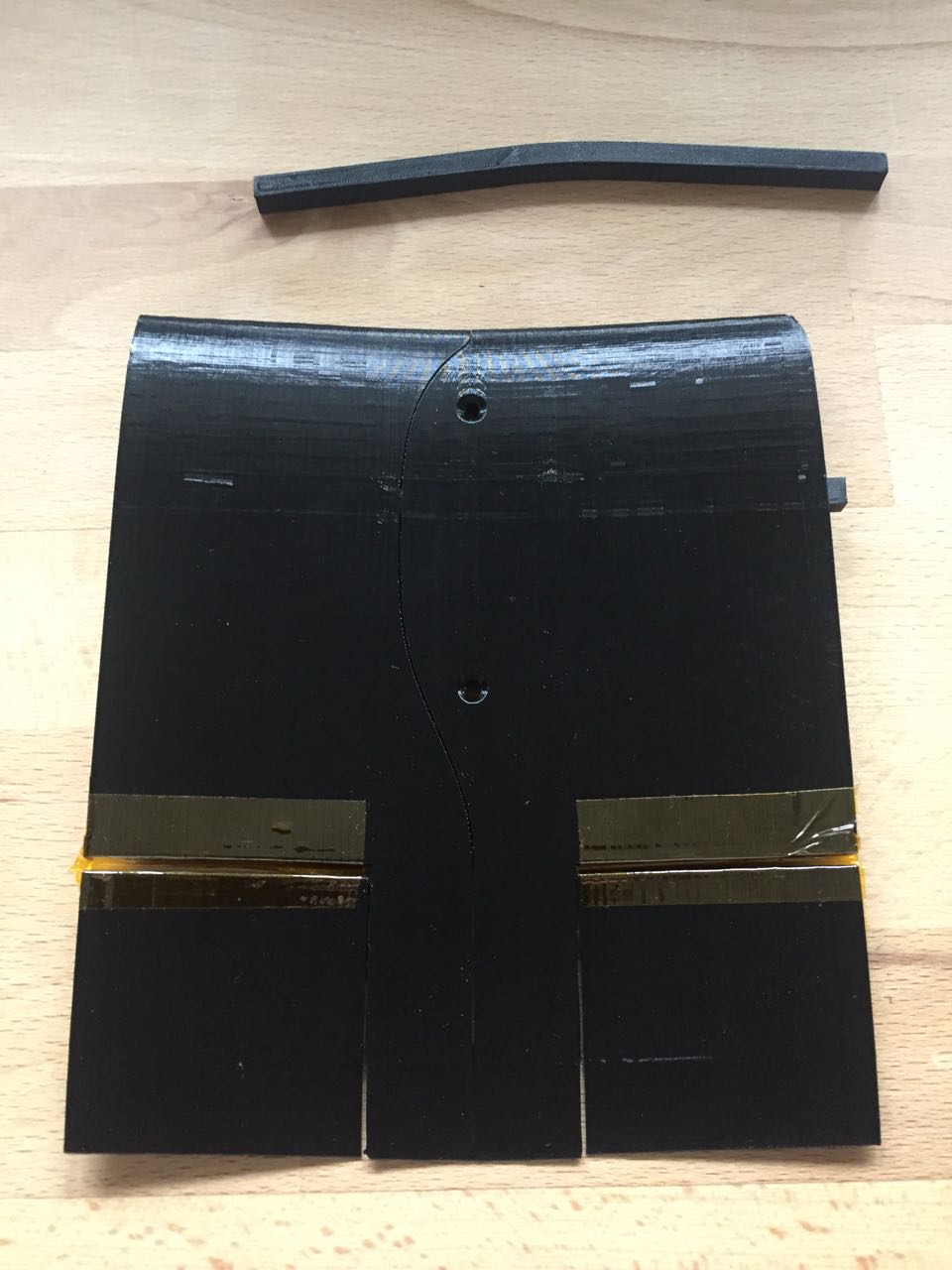
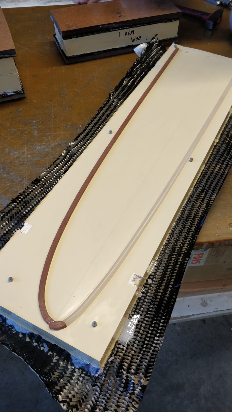
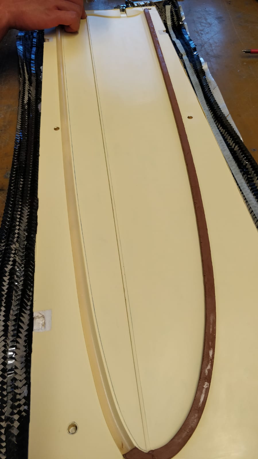
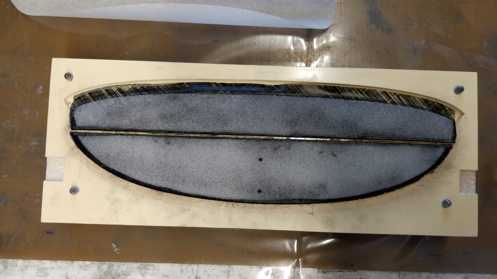
2.4 Wing joint
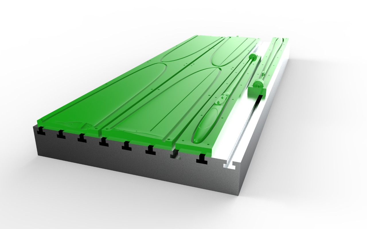
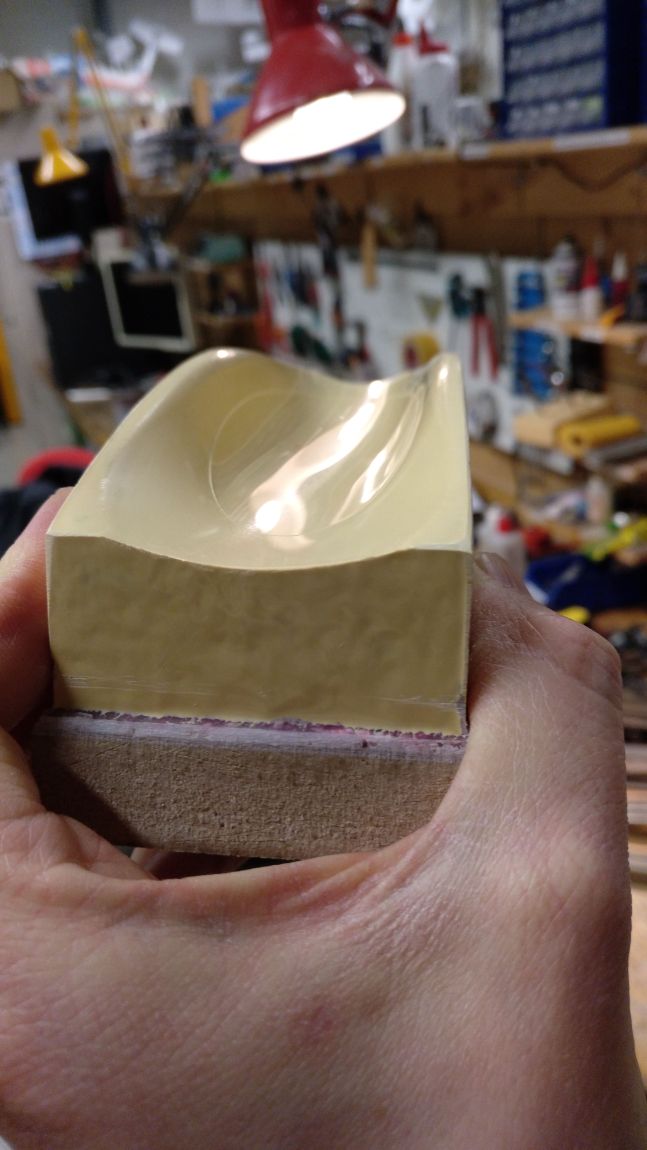
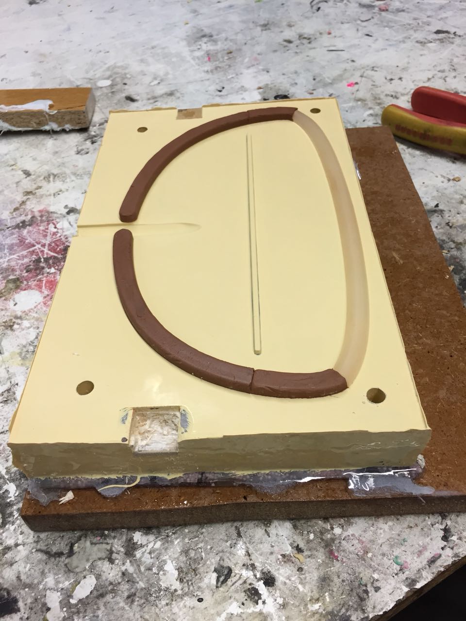
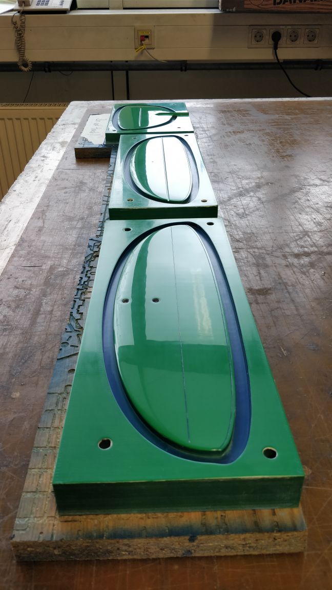
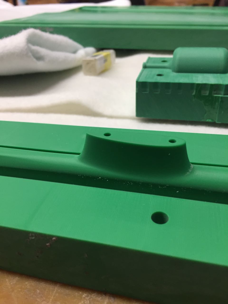
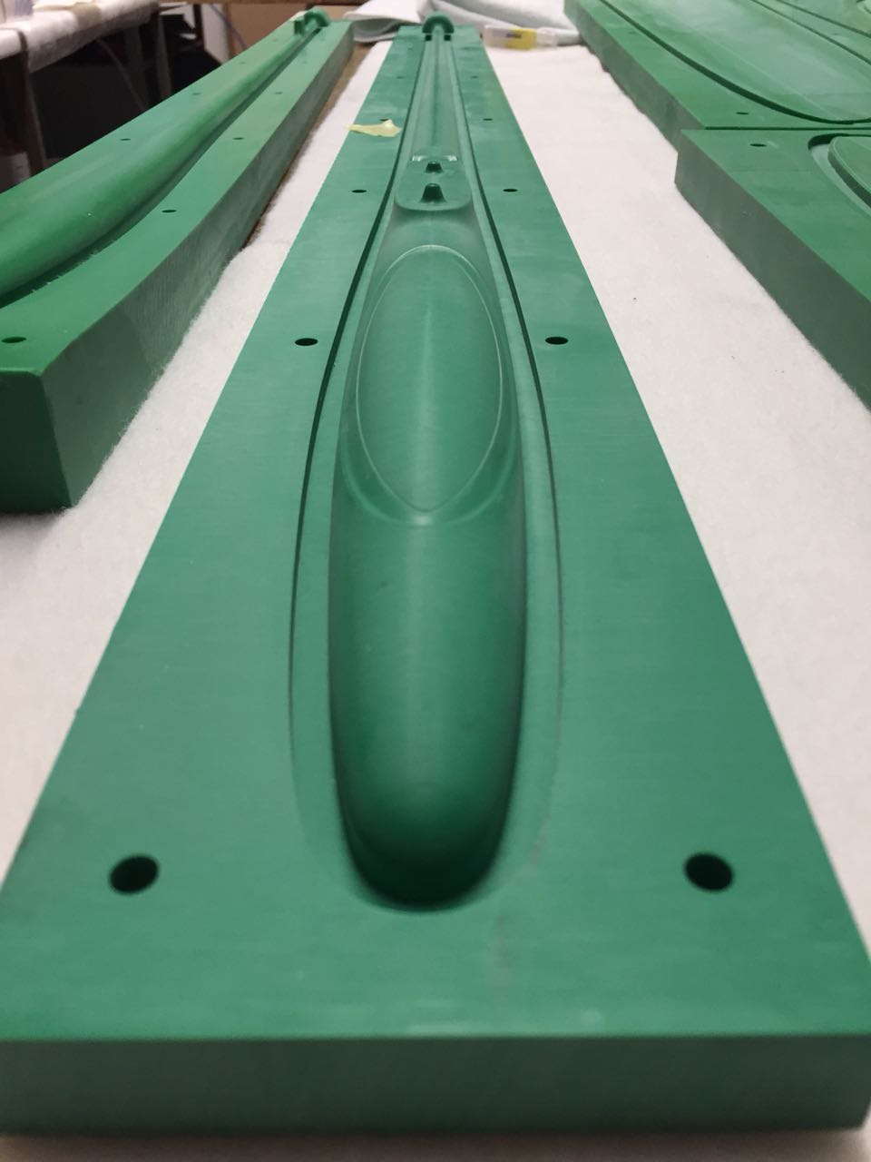
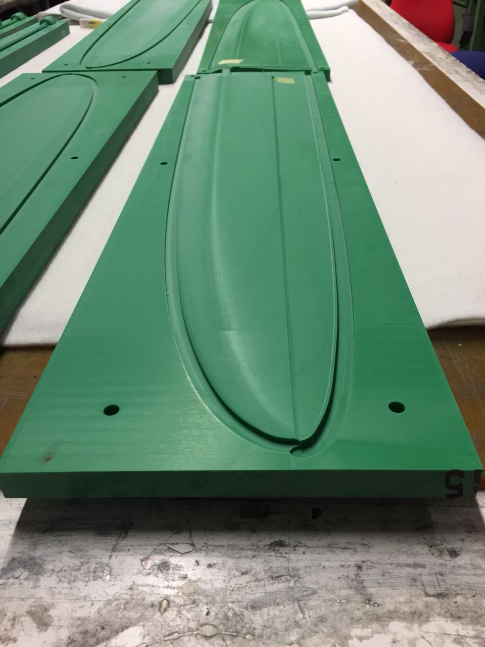
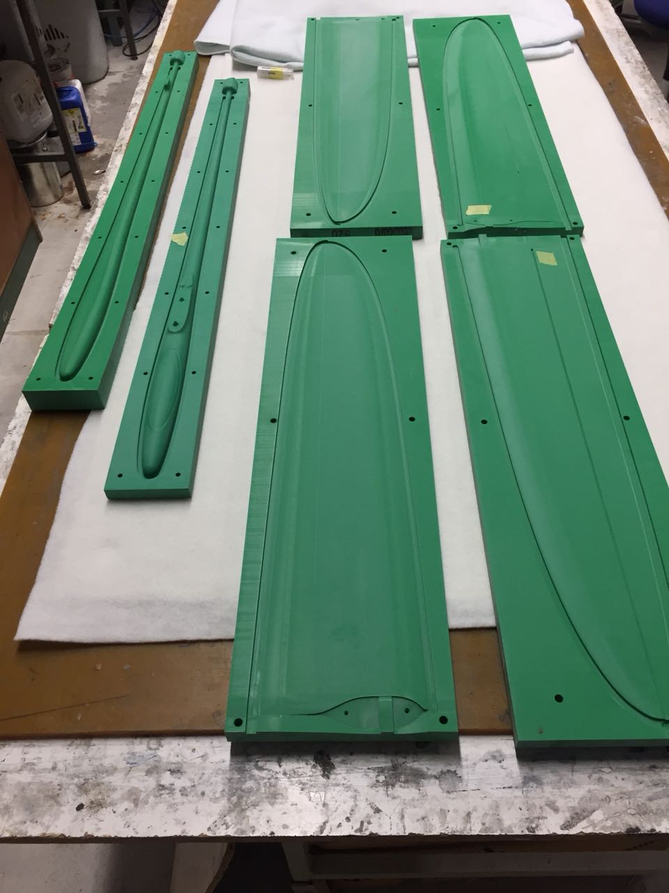
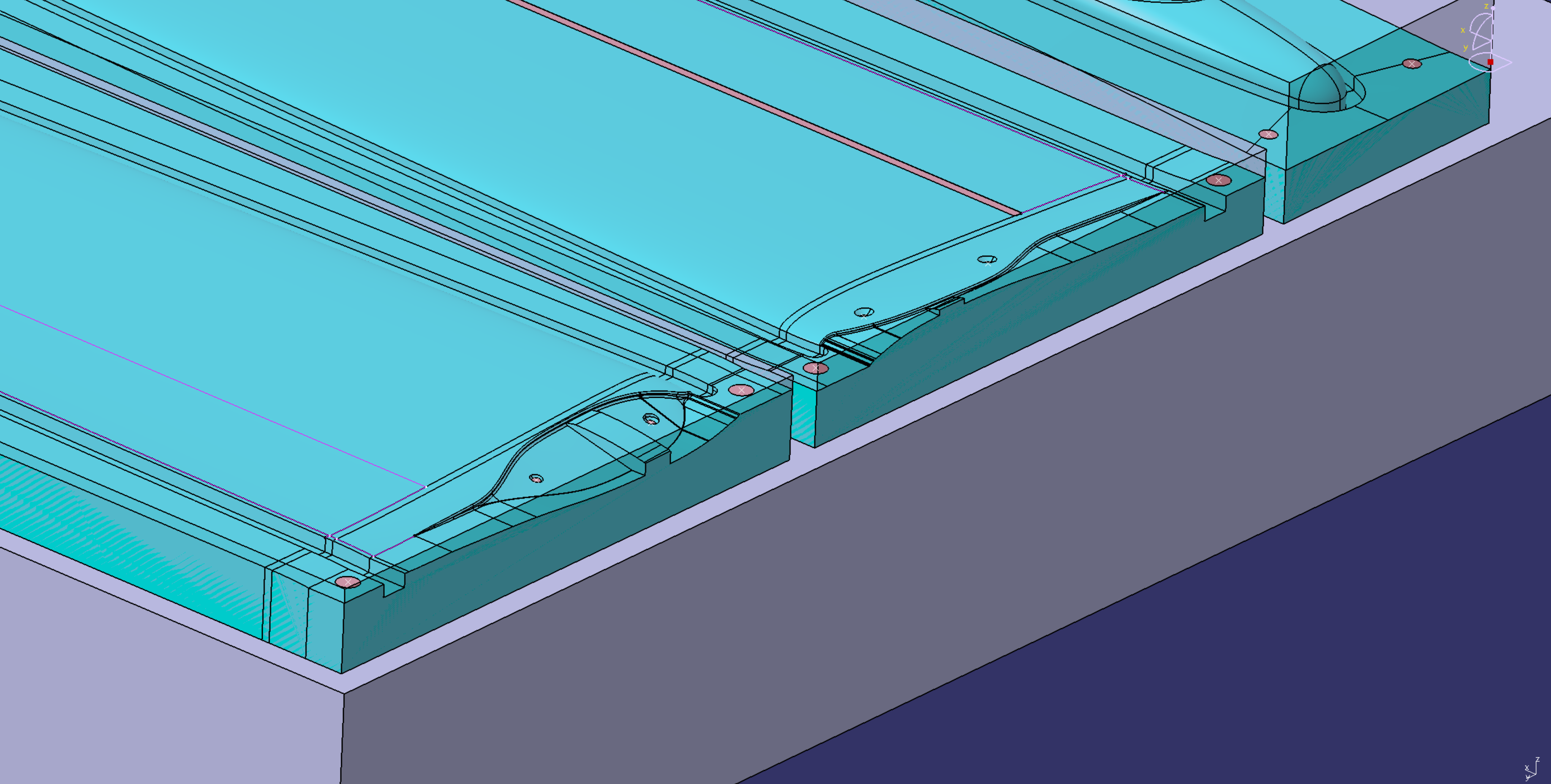
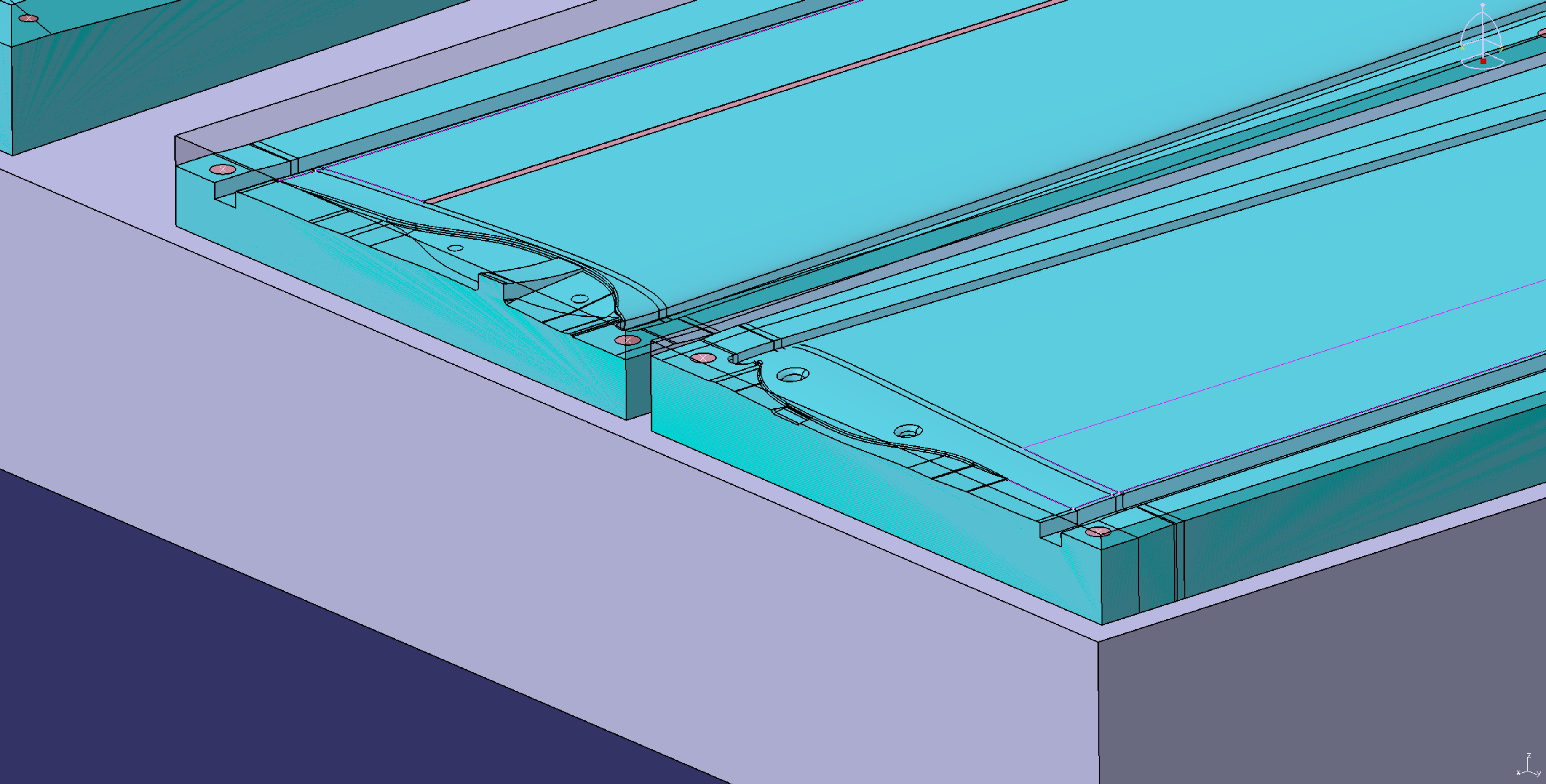
I’m sure this is one of the most interesting details of the glider. Here I have some images. The yellow ones were made earlier to show to my team members and only show the concept. The renderings with the green canopy show the actual wing root design, but no joiner installed yet! For now please add the joiner from the pictures with the yellow design to the green ones in your imagination ? .
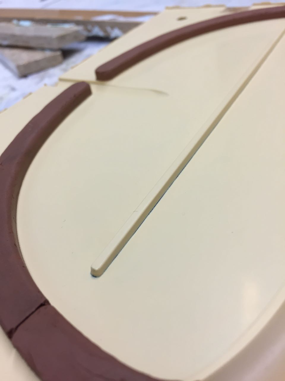
We think that this kind of wing root can be built in the molds quite well. Of course, the wing halves need to be built separately. The joiner pocket could be built directly wet-in-wet with an insert when closing the wing. In the other wing, the joiner is glued directly during mold closing.
We are still about to calculate the spar layup, so the thickness and length of the joiner are also not fixed yet. Work in progress 😉

___________________________________
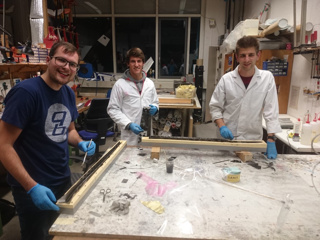
After lots of theoretic stuff we can show some results of our prcatical work.
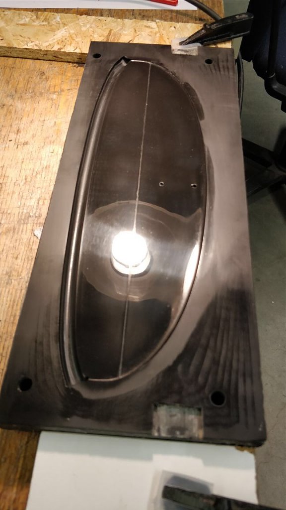
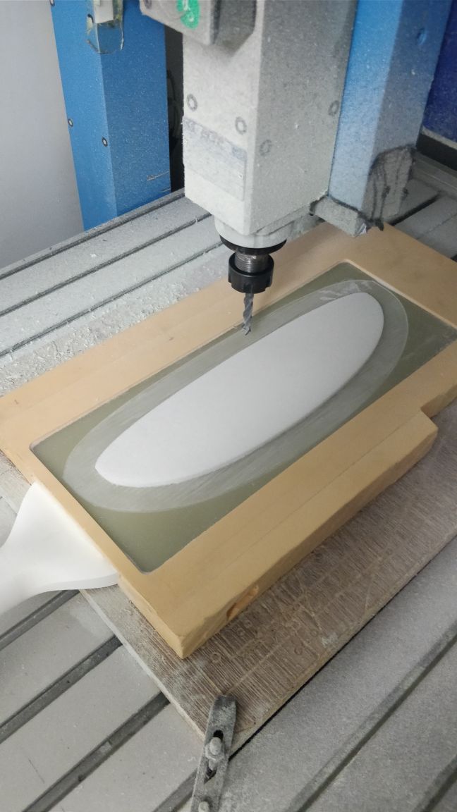
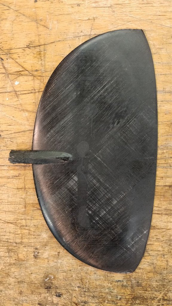
The first mold of the project was milled yesterday! The elevator is the most straight forward part of the project, so it’s a good piece to start with. For some reasons we make a positive, from which we build the manufacturing molds: We do not have a strong enough machine to make aluminum molds. Aluminum molds are also sensitive, so those would be too expensive to give them to the rather inexperienced guys of our team. Also, we will build carbon fiber production molds to have the possibility to do some out-of-autoclave prepreg tests – once we can get the material. The mold material is about density 1000 kg/m³ and we finished the surface with 0.2mm path distance. Next steps are sanding the mold up to 2000 grain and then polish it. In the next days, we will mill the mold for machining the rohacell core for the elevator. We have had some nice ideas how to make production as simple as possible 😉
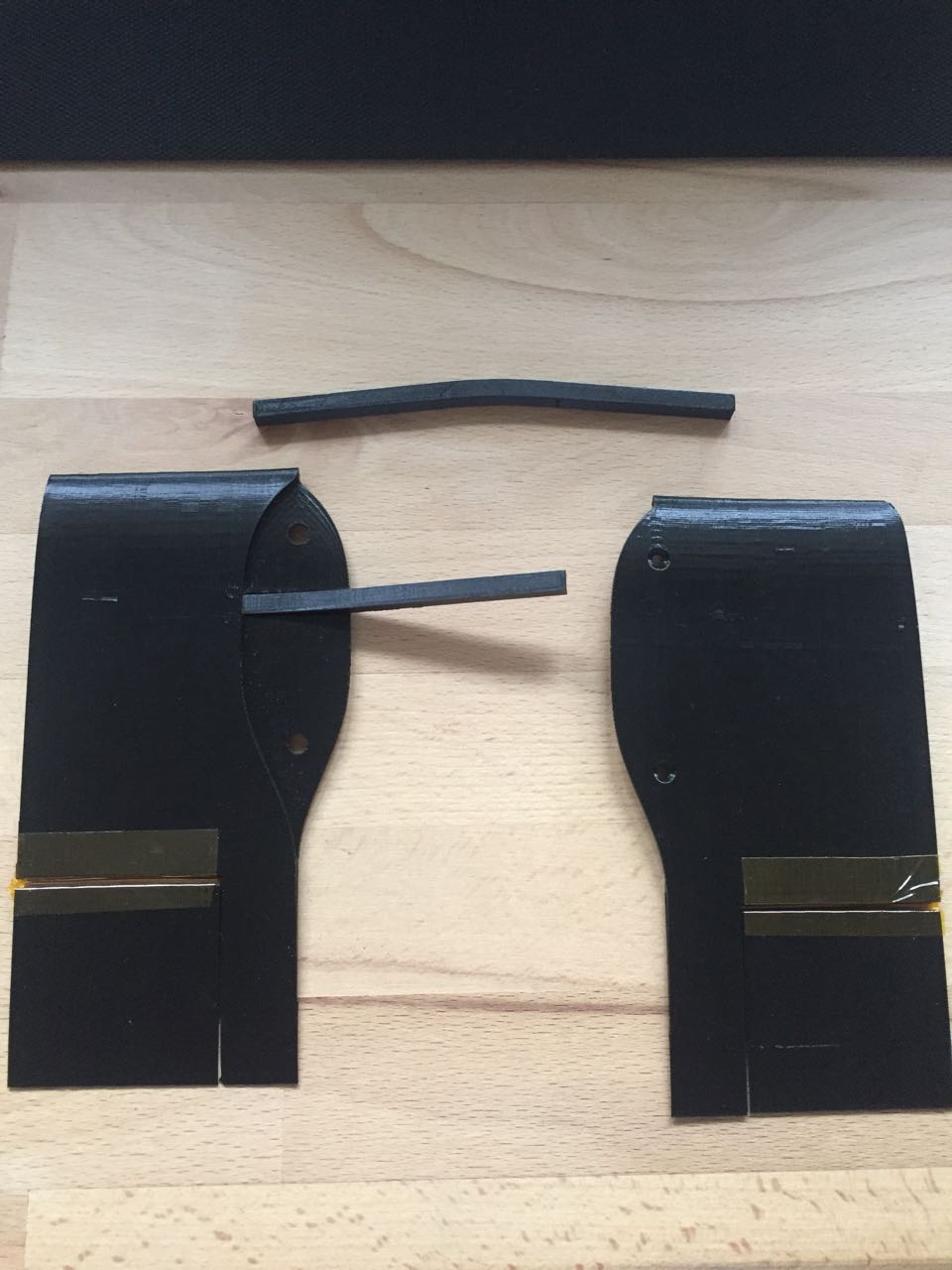
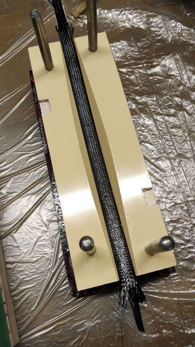
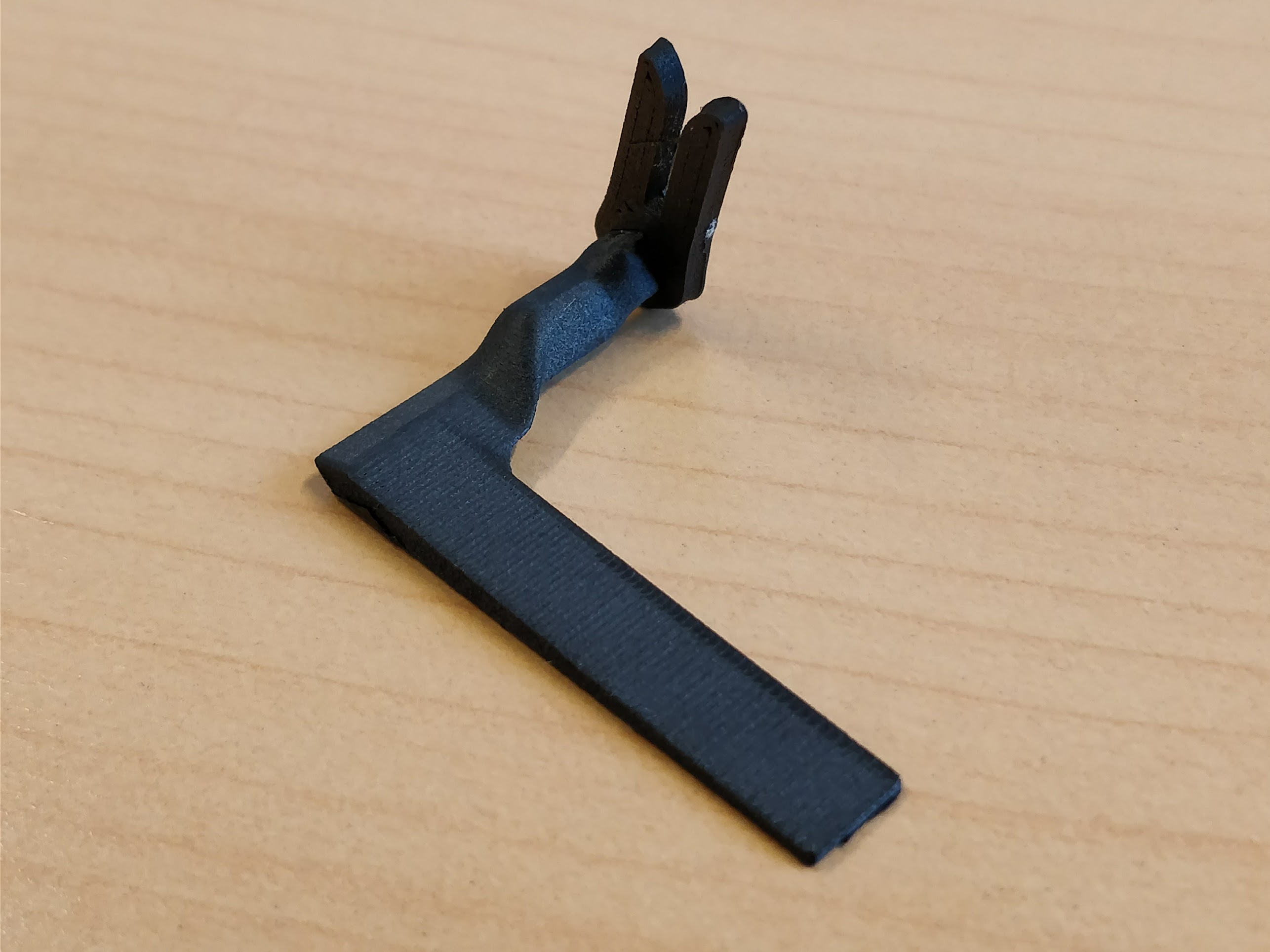
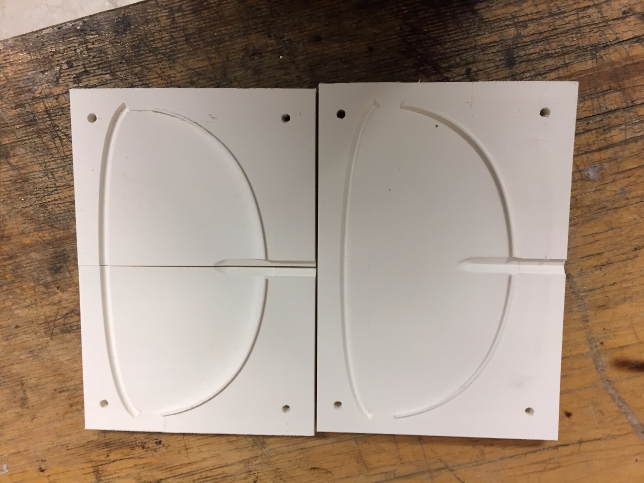
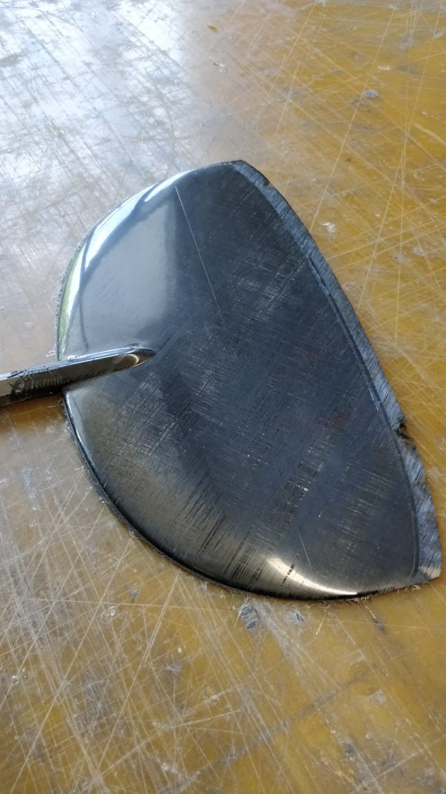
Because of the uncertainties with the two-piece wing, we test the wing root and the connection system. First step was to simply 3D-print the wing root parts and a joiner. Second, we will 3D-print molds and build test pieces of the wing roots and the joiner, like we would do with the actual molds. Only if the build quality and the strength of the parts are pleasant, we will advance and mill the wing master molds.
The same type of testing will happen with the fin and the idea of using an Allen key as insert and having a hexagonal fuselage end. We will see if it works out…
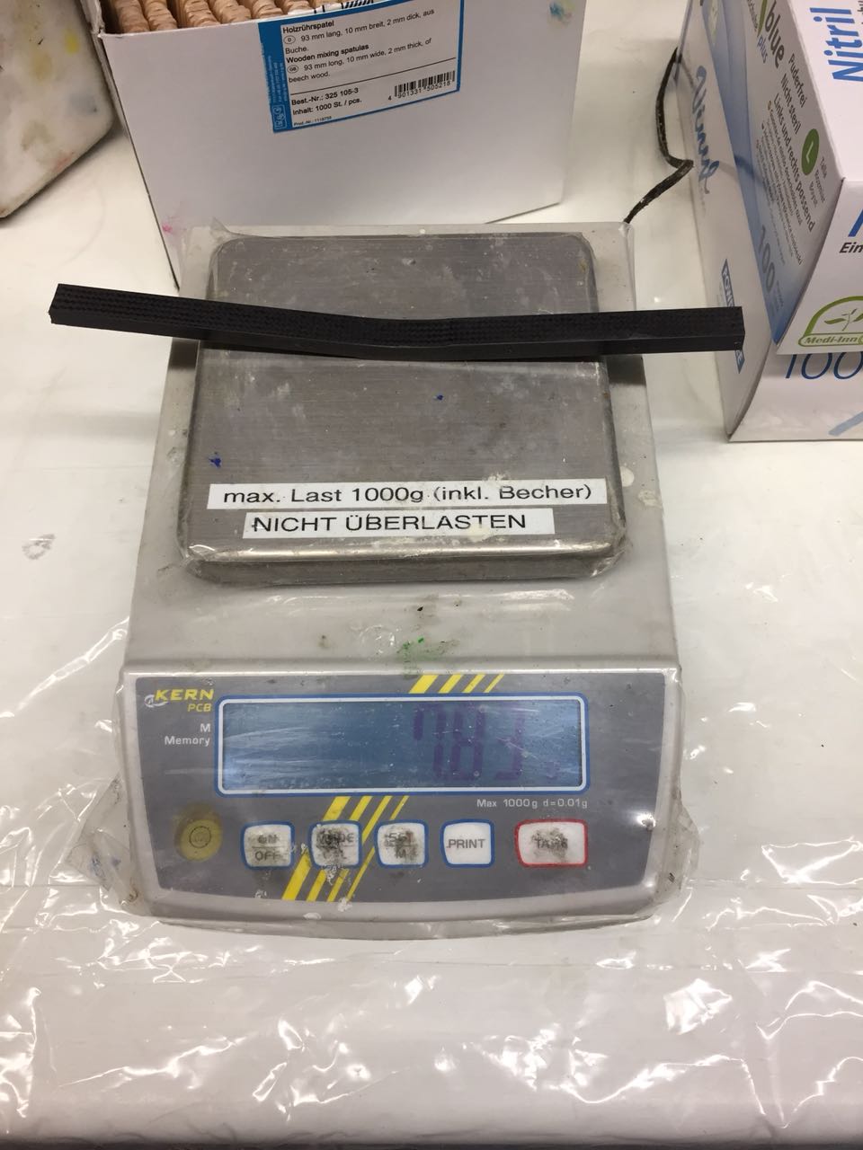
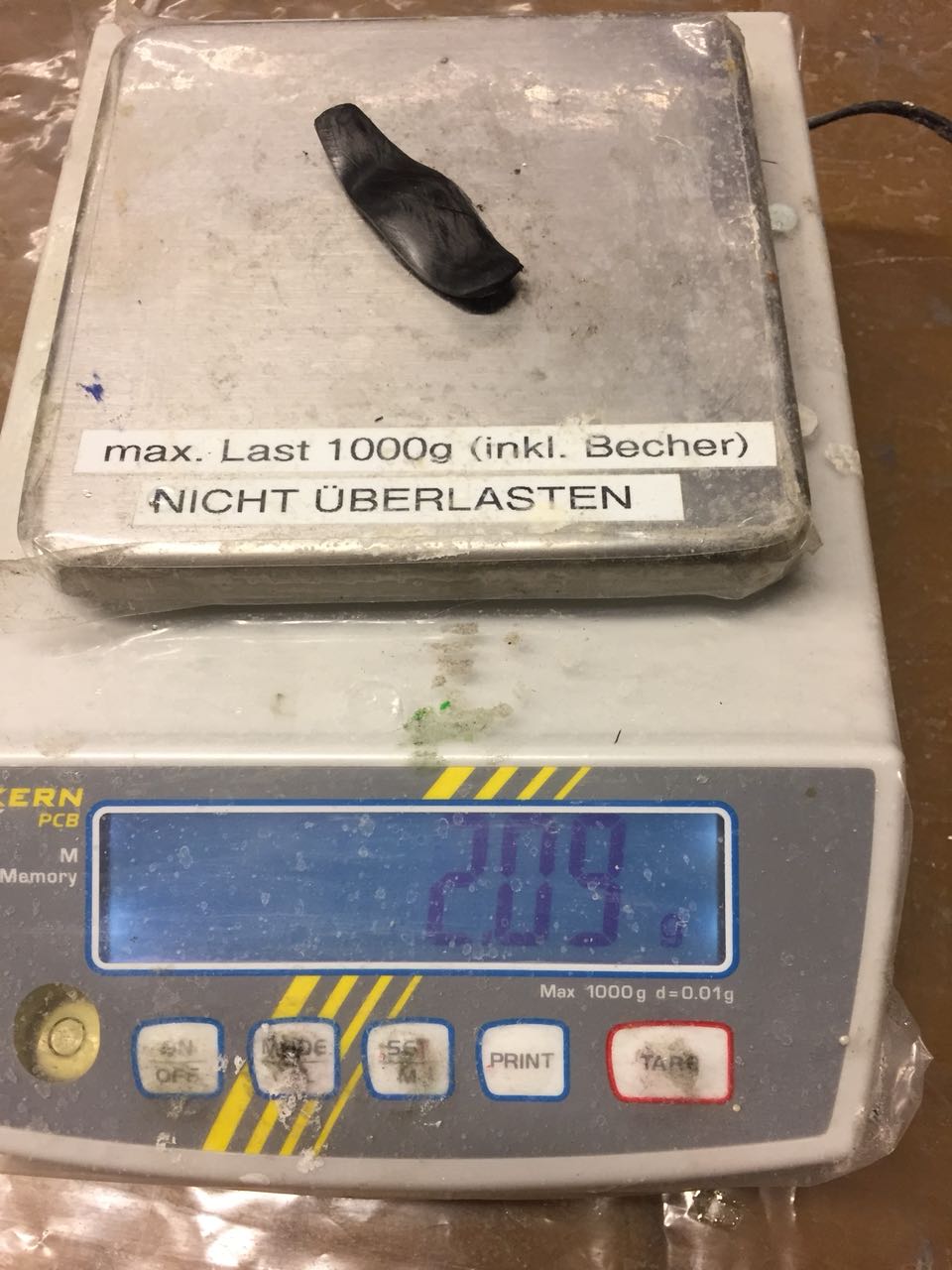
We also made some pegs to test. Astonishingly, we found that 50% infill PLA pegs already can take 15kg load tests. A full infill peg will even take a little more. However, I think we will switch to carbon pegs once we like the shape. But for light DLG’s or 1m models, 3D-printed pegs might work fine!


_________________________________
It’s been a while since an update here, but there is some great progress in the project. First, I would like to give you some insights to the origin of this project and then talk a little bit about the financial background of the project. Remember: This project does no pursue any commercial background and we don’t want to earn money with our plane. But material for molds and prototypes must be paid as well.
So how does it work out for us?
On our trip to lake Garda this year, we had the idea of designing a new F3K plane, which fits our requirements for flight performance and transportability. After some brainstorming, the project became a specific idea and we put the project to a vote. Every project which is started as project of our organization has to be voted for at a member gathering. After having no votes against the project, the inconvenient question “who is going to pay for it?” came up.
The AkaModell Munich is a student association which is financed through yearly membership fees and tuition fees. The membership fees roughly cover up the consumable materials in our workshop (like glue, cutter blades, gloves, drill bits etc.). The tuition fees must be requested every semester and are not enough to finance such big projects entirely. Additionally, we just finished the “Air Cargo Challenge 2017” which also took some money out of our pockets.
Luckily, there are people and organizations out there who support such student projects with sponsoring. There are many types of possible support. Next to pure financial support (which is rather offered by large companies in industry), there are material sponsoring or free services, such as milling molds, or giving a discount on products.
At our side, we try to counterbalance the sponsoring by various means: Of course, we make the sponsoring partnerships public on our website, facebook page, German RC printed media, student news papers etc. Also, some of our former active members now work for former sponsors or have a b2b customer relationship to them, because of the positive cooperation in the past. Also, we have connections to the research institutes at TUM university, which are also a potential customer or partner in our sponsor’s projects.
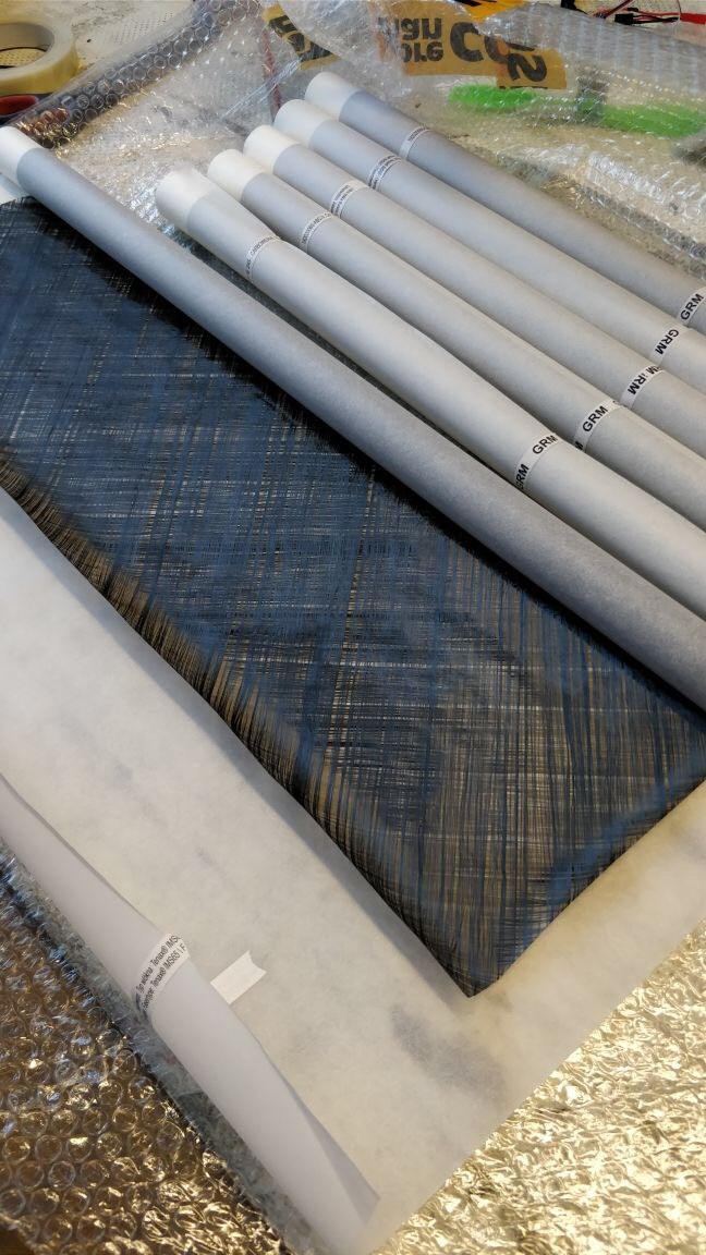
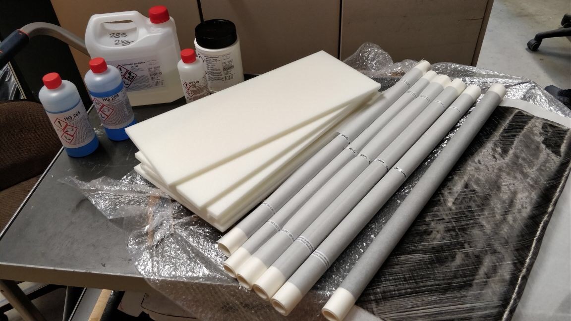
So, we are very glad to win GRM Systems GmbH as our sponsor and partner for this project! Stefan (rc-network user: Gideon) contacted us and offered in shape of material for the project.
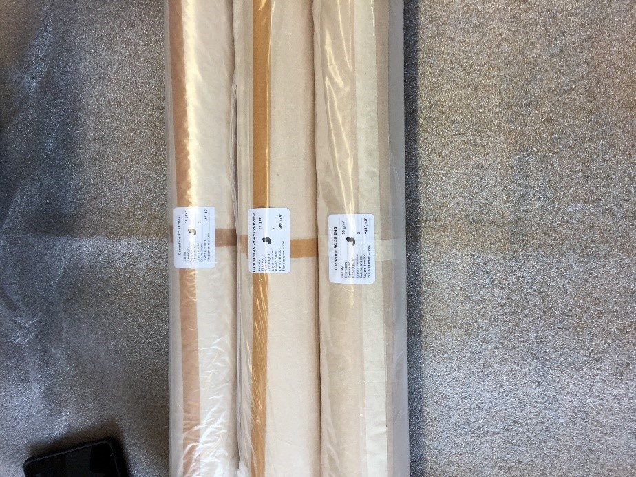
After a very positive and detailed discussion with him on the telephone, he put together a package of materials. This included a polishable and styrol-resistant molding resin, an alternative resin to our L285, lightweight biaxial NCF with 16, 20 and 30 g/m² as well as a Rohacell-like PMI-foam with 29 kg/m³ density.
Thanks to the generous parcel we have enough material for prototypes and can start building the first parts
A big thanks to GRM Systems GmbH for their support!
Without support from the industry, a lot of our projects would not be possible. If somebody here has ideas how to support the project, don’t hesitate to contact us!
The first empennage prototypes will be build in the next days and we are excited for the first results! I will shortly write a seperate post about the progress from the last days.

_______________________________________
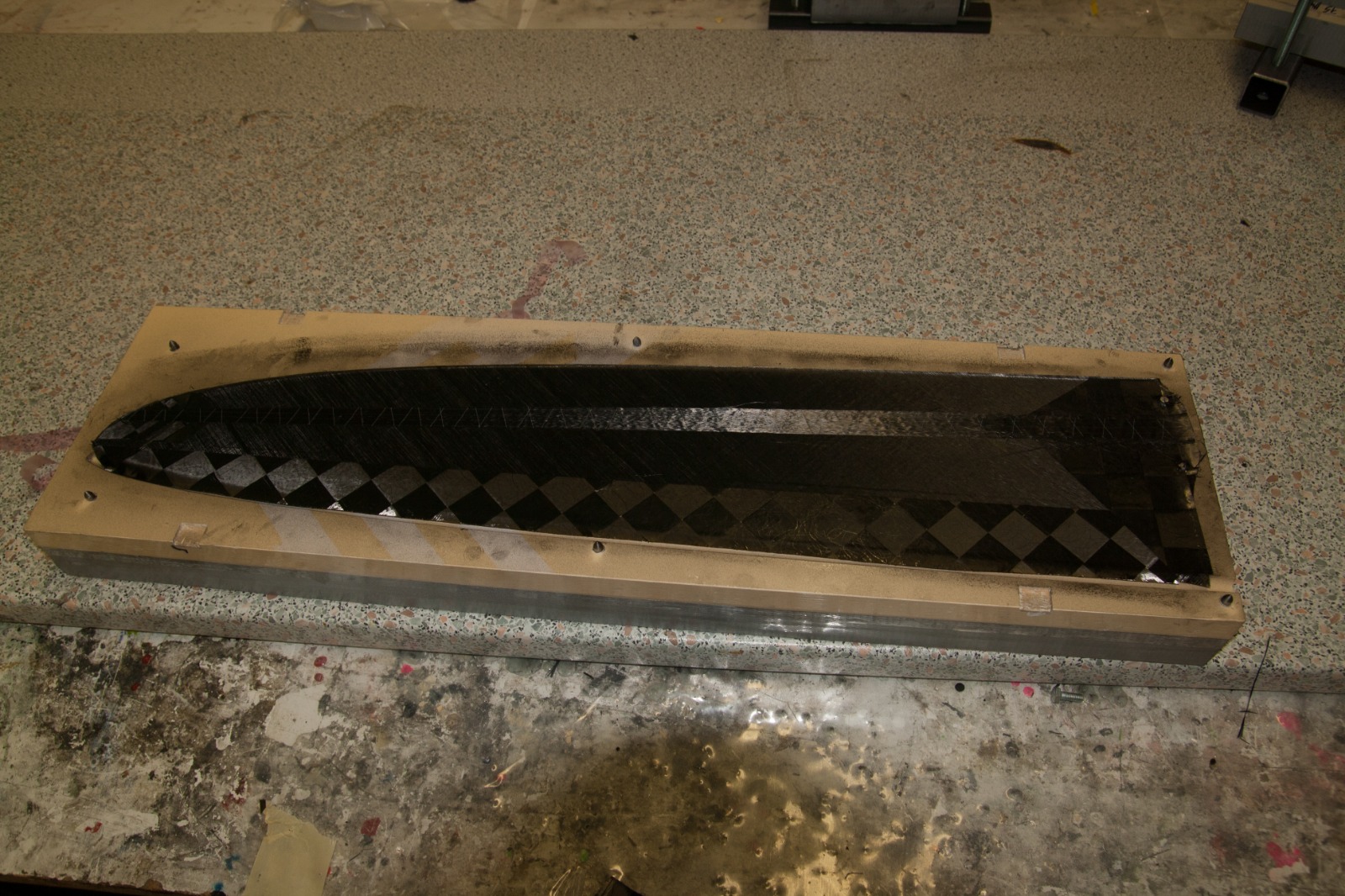
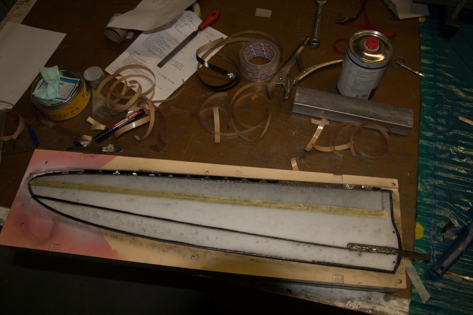
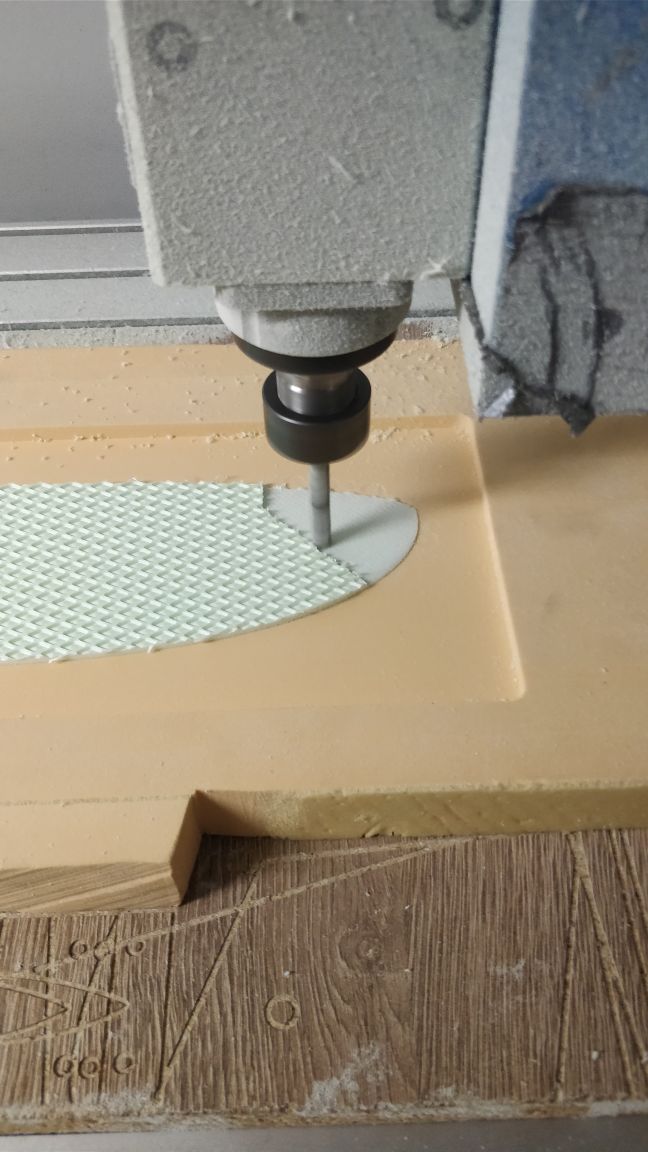
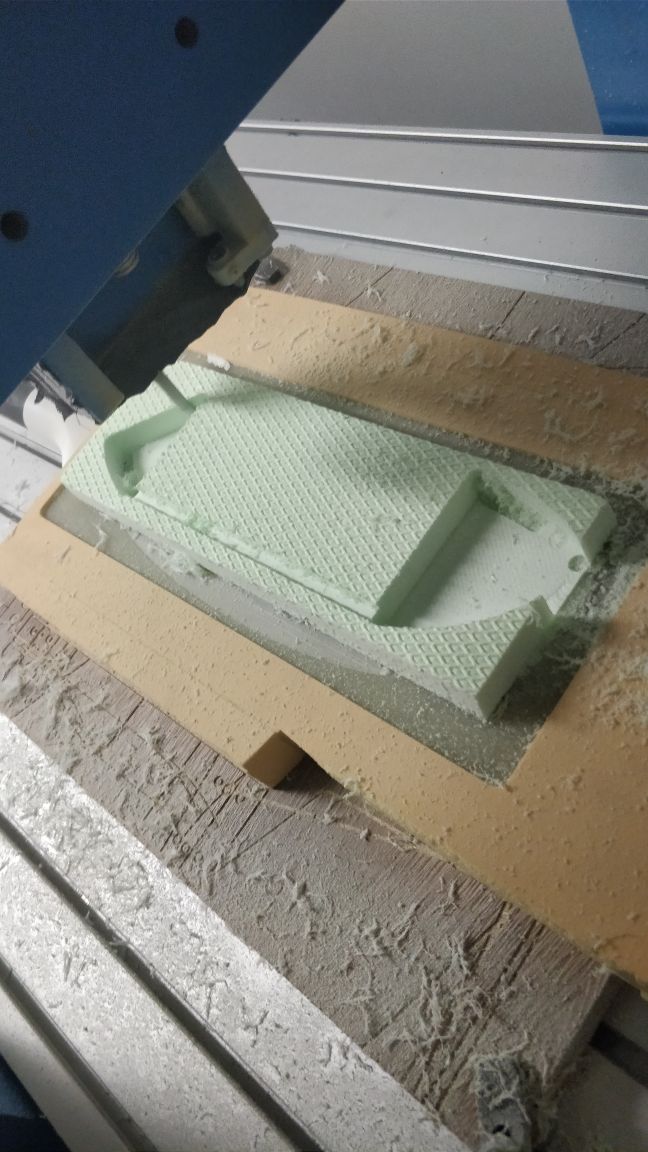
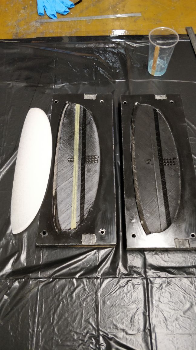
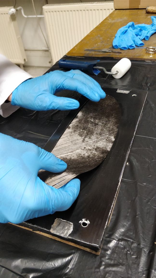
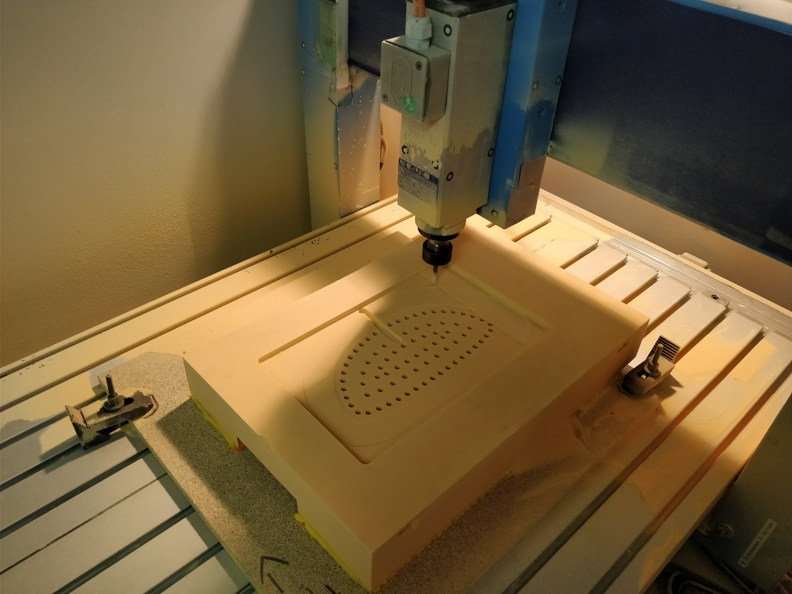
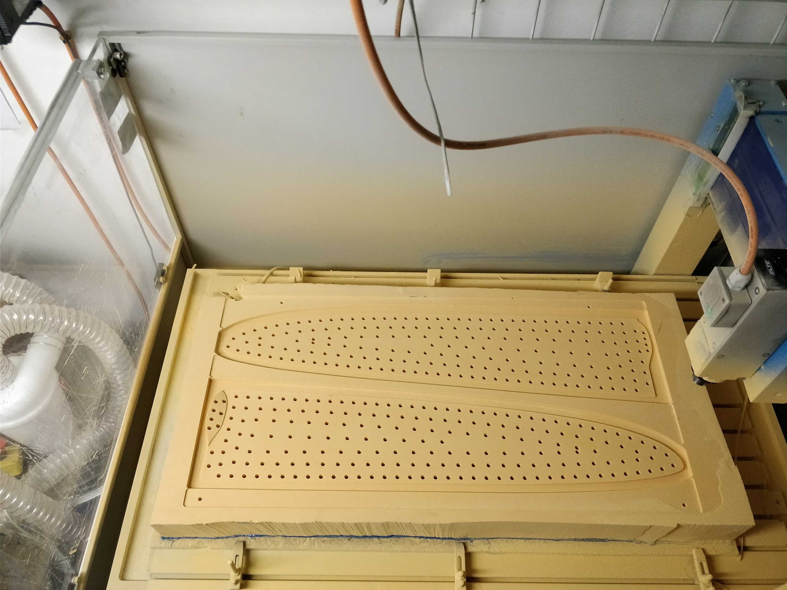
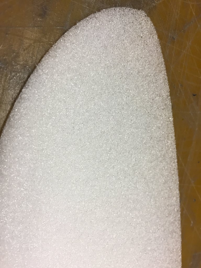
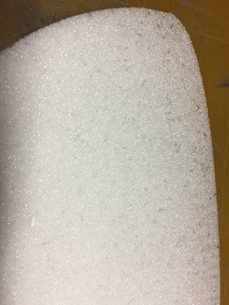
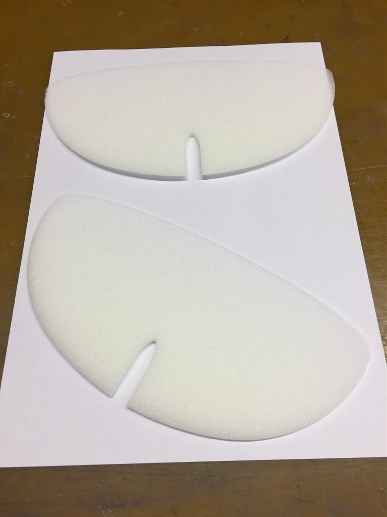
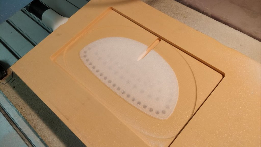
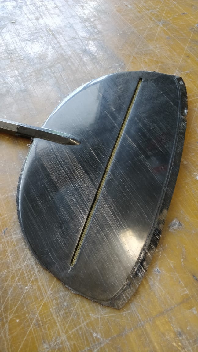
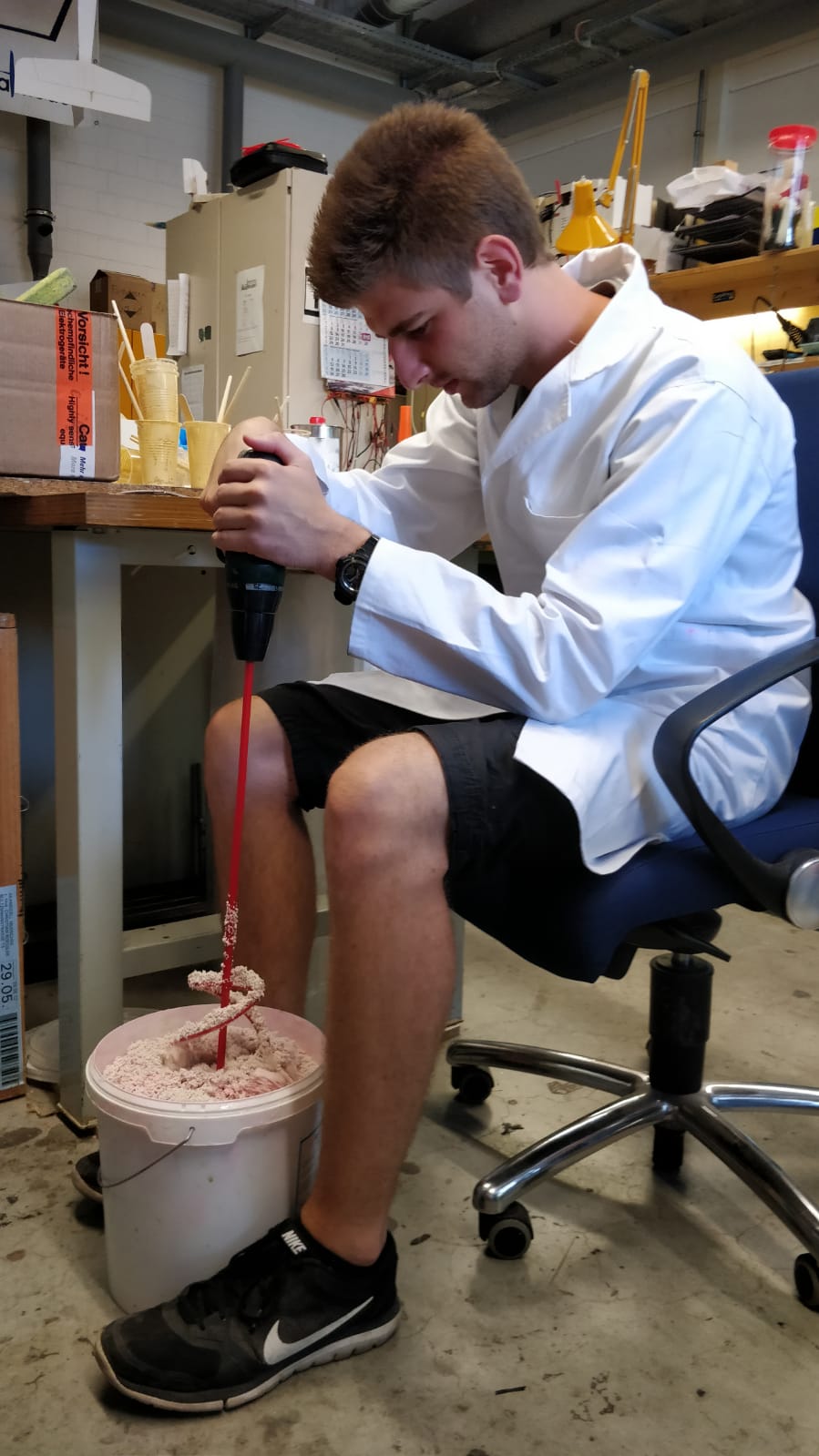
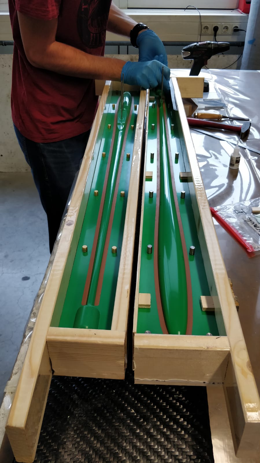
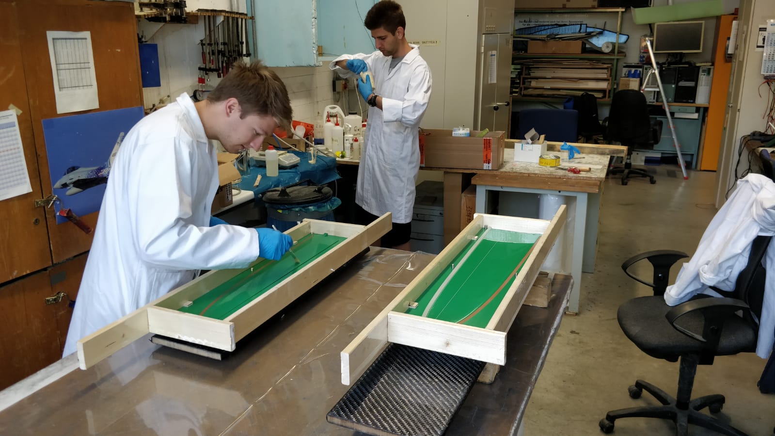
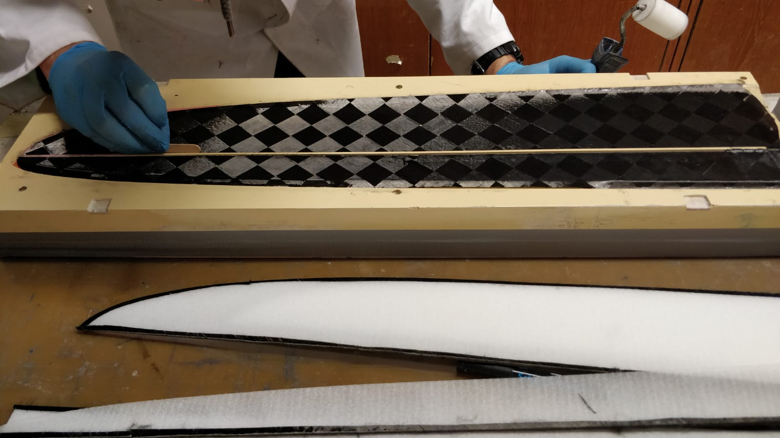
There is a lot know-how already out there, how to make double-sided milled foam cores. However, we can not claim to have worked with this technology extensively so far. There is still a lot of experimenting coming up! Here are some photos of our first elevator core milling. The toolings and processes are designed to enable our less experienced members to manufacture cores on their own, without much experience. I think once we have figured out the complete process, I will make a dedicated posting on core milling. Concerning the two-piece wing, this will be quite interesting.
In the pictures, there is a first test with inexpensive foam, my team mates afterwards adapted some parameters and milled the second core from the foam, which we got from GRM.
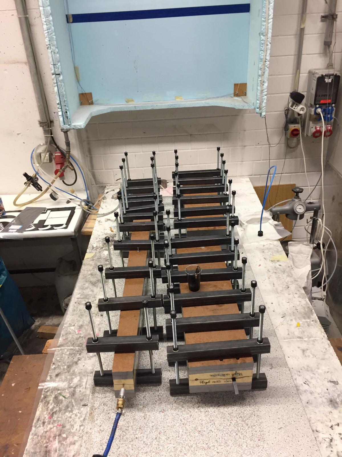
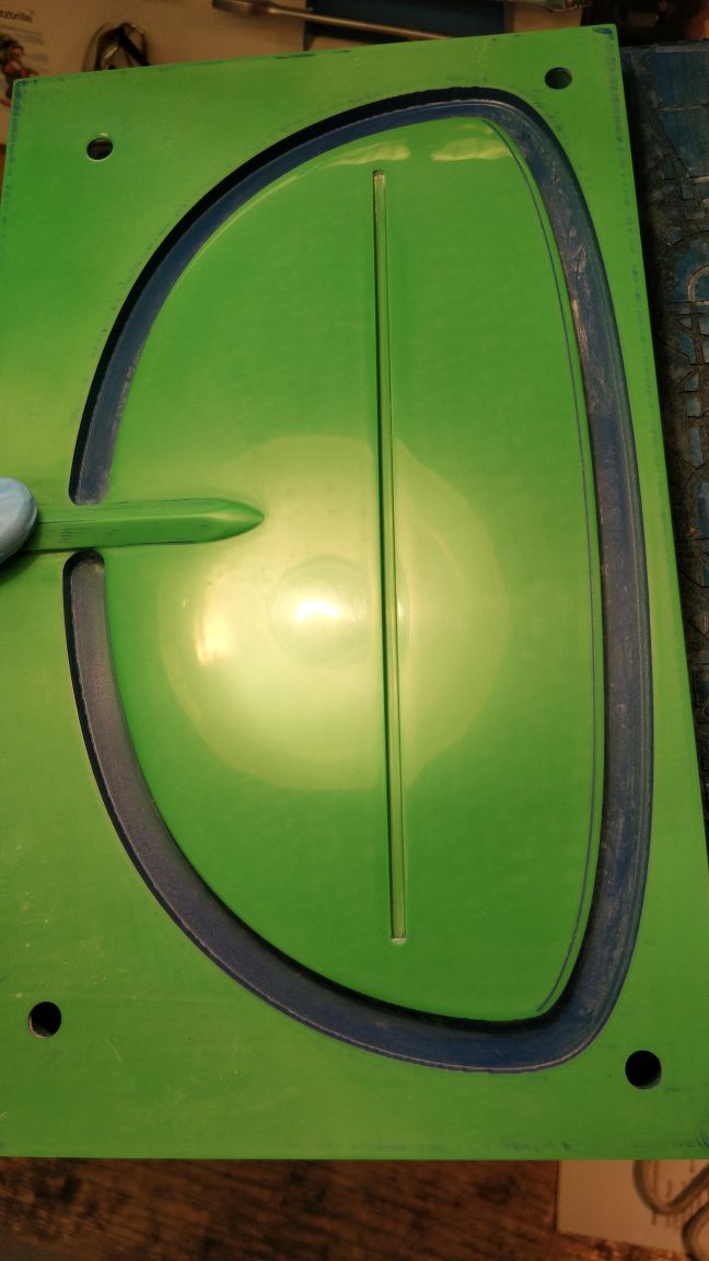
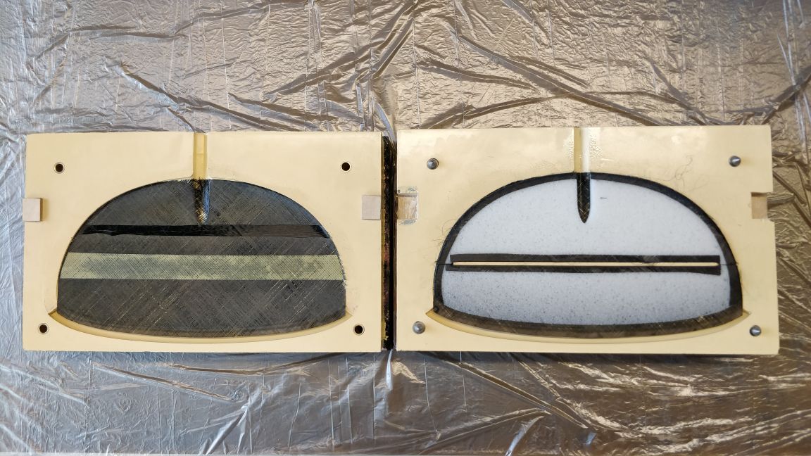
We also built the first set of elevator production molds. The molds are built with molding resin, glass fiber layers (2x 50 g/sqm and 2x 100 g/sqm) and then three layers triaxial carbon fiber (each approx. 1000 g/sqm). The silicone string is removed after demolding and gives us a nice grove to handle the excess fibers from the empennage skin at the trailing edge. We use wax release agents.
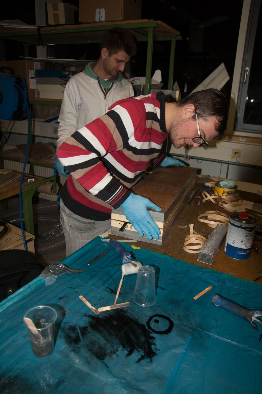
Right now, the other guys of the team are building the first elevator from the GRM materials. We also prepared pre-laminated kevlar hinge pieces, which are laser-cut! I am looking forward to see the very first piece of the airplane in the next days. I hope someone took pictures today, so that I can share them with you soon.


________________________________________
Hi everybody,
since it was Christmas, the project was paused for two weeks. But now, we have already begun working with full force again and I can give you a little update on the project progress. Meanwhile, the CAD surface design was finalized. There was lot of discussions going on in the team about many details. Right now, tooling design is in its final stage.
One of the major points was the making of the wing and fuselage molds. We decided to make all molds from aluminum, including redoing the already existing elevator molds. The plan is to recieve the machined molds back by beginning of march.
I plan to make several posts here as soon as I have enough time to prepare them properly. One will be about our core milling technique, which works excellent by now. Another will reveal the calculated aerodynamic performance (including polars!). Maybe i can also make a post on our mold design, which might be interesting to some people here.
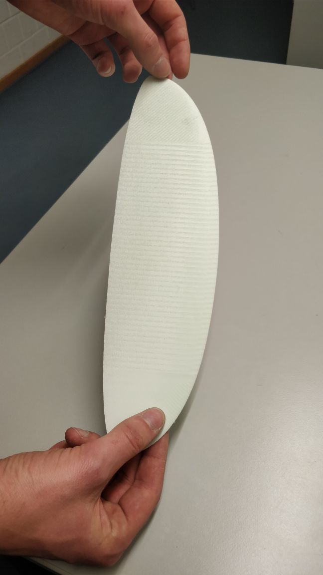
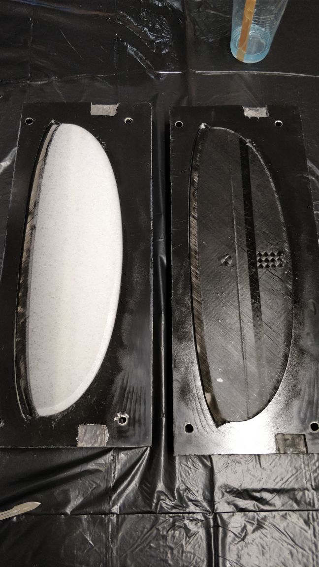
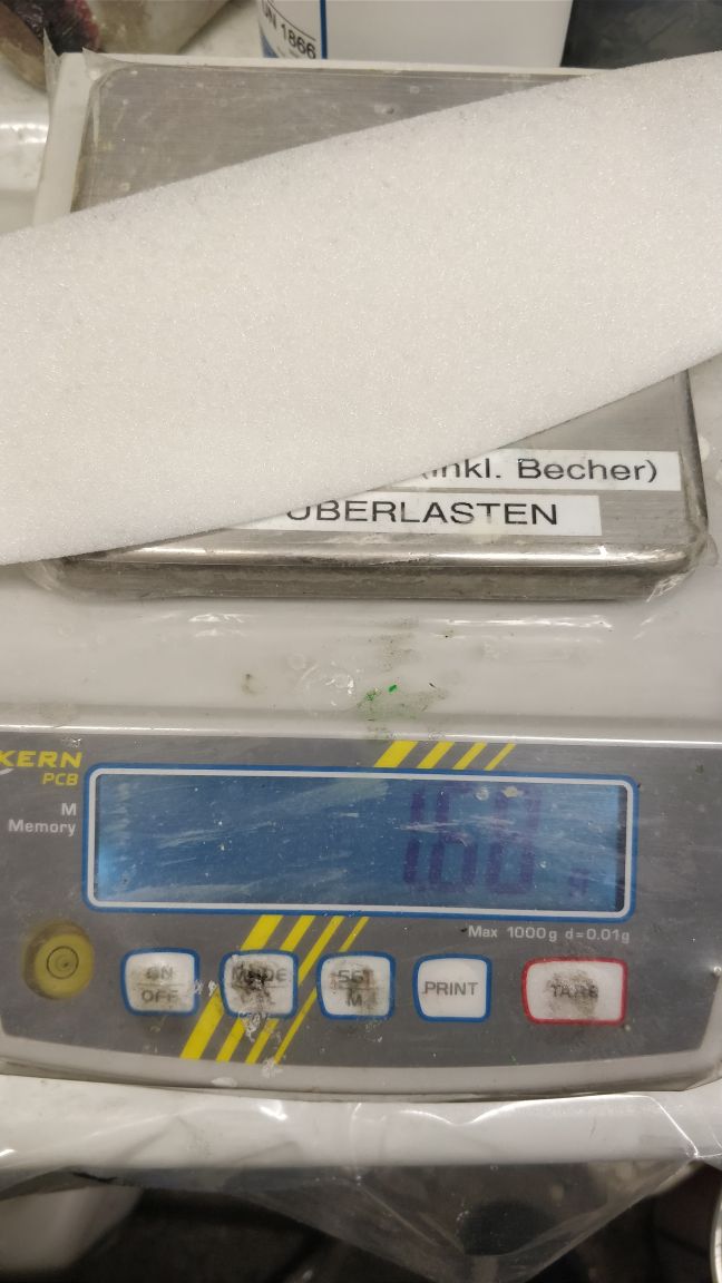
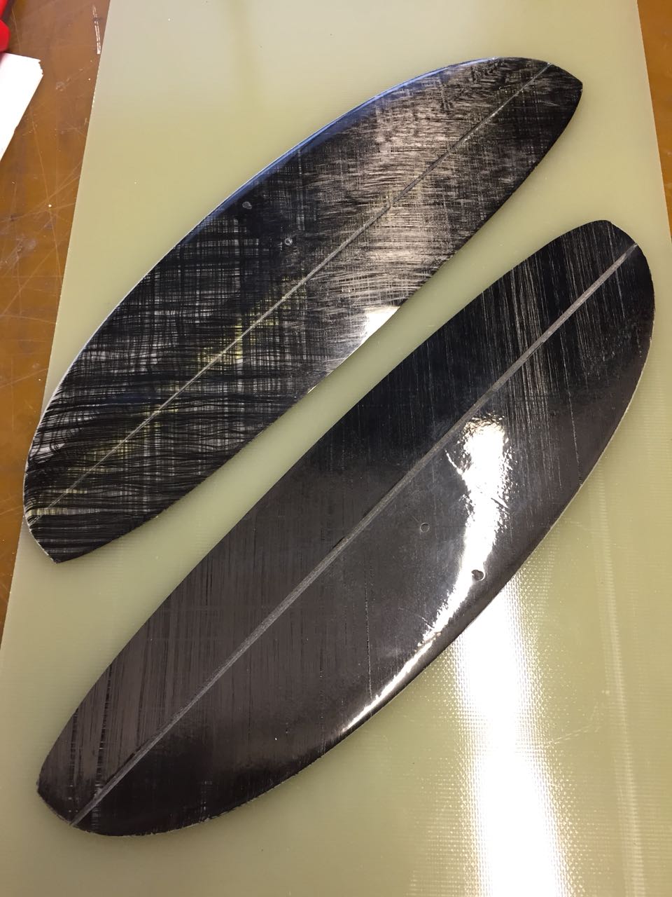
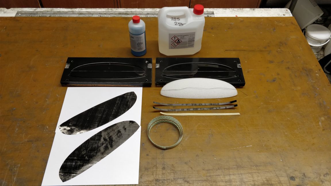
I will attach some pics: We have built the first elevators from our carbon molds with the materials, that we recieved from GRM. The two elevators were built with 20 g/m² and 16 g/m² biax carbon and the core was milled from the PMI-like 30 kg/m³ foam from GRM. We used transfer tape and 27 g/m² glass fiber to close the skin at the seading edge. The elevators turn out at 5.2 and 5.4 g – and we did not attempt to save as much weight as possible! The surface quality is really nice, even for the 16 g/m² skinned piece.
We also made the core milling tools for the fin. We made a set of 3d printed fin molds to test the idea with the allen key insert. This will also be one post coming up soon!
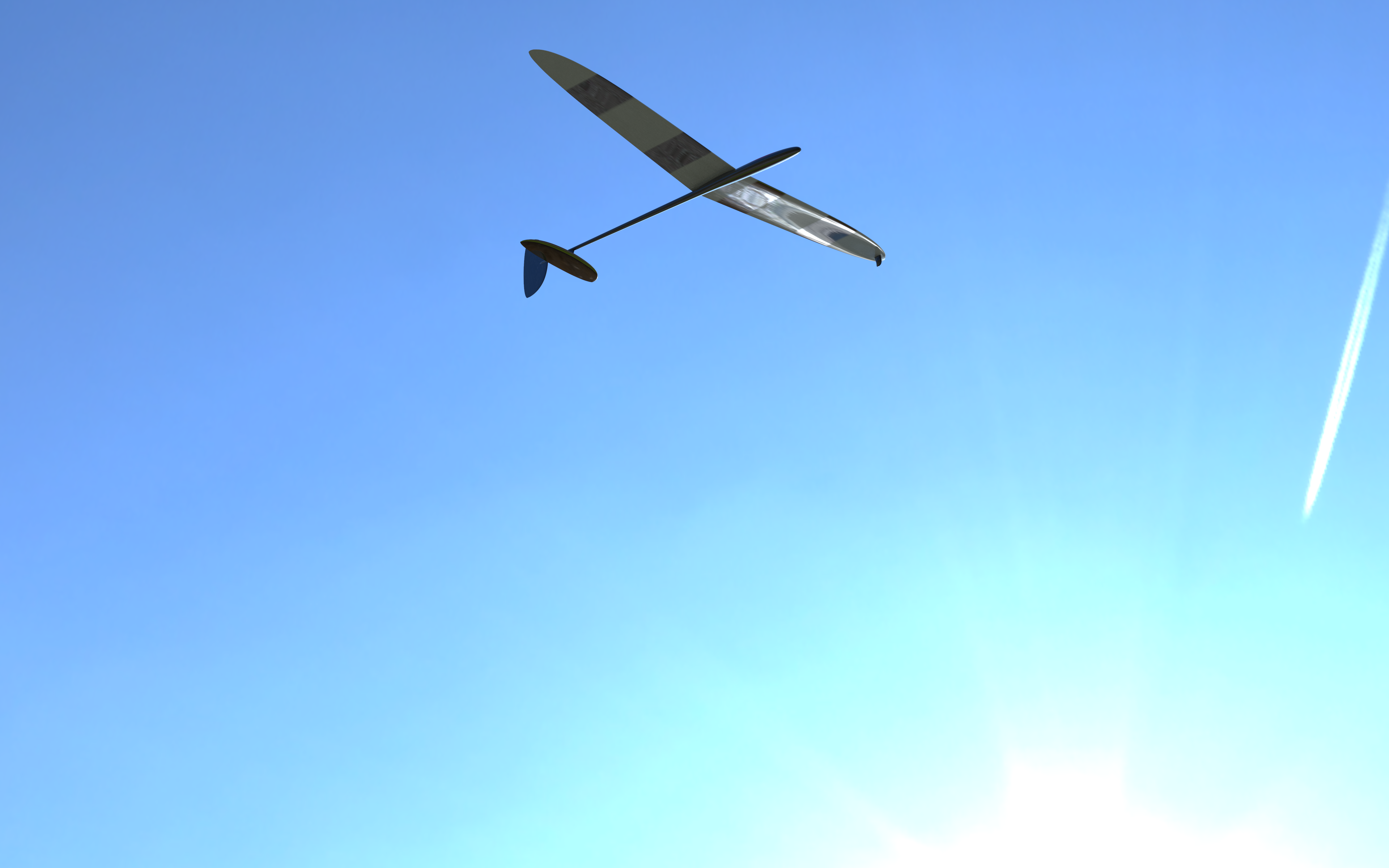
Finally a new rendering with the airplane, a treat to motivate our team to keep things going!
_______________________________
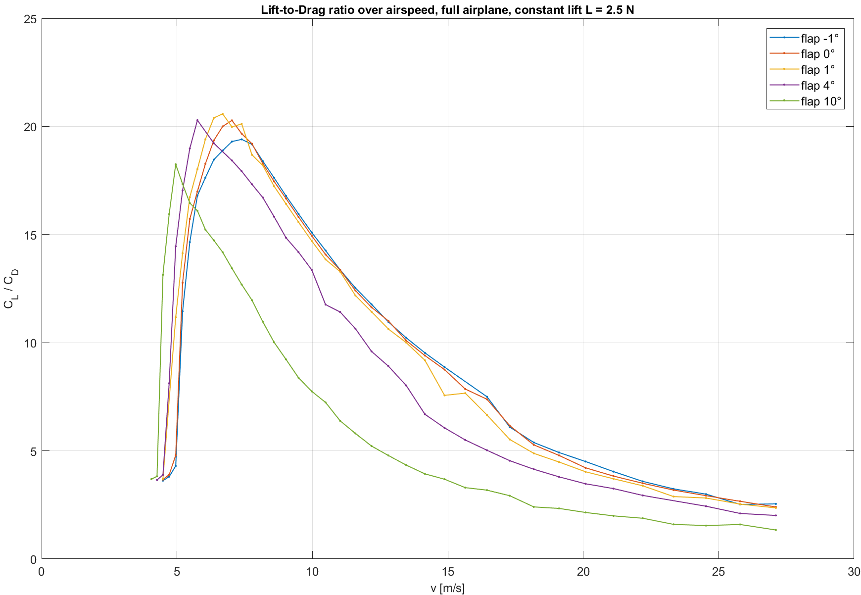
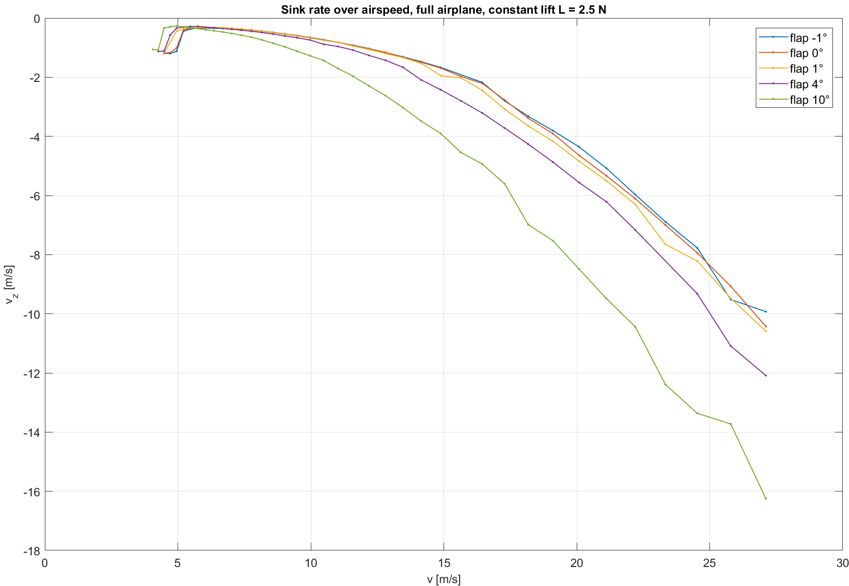
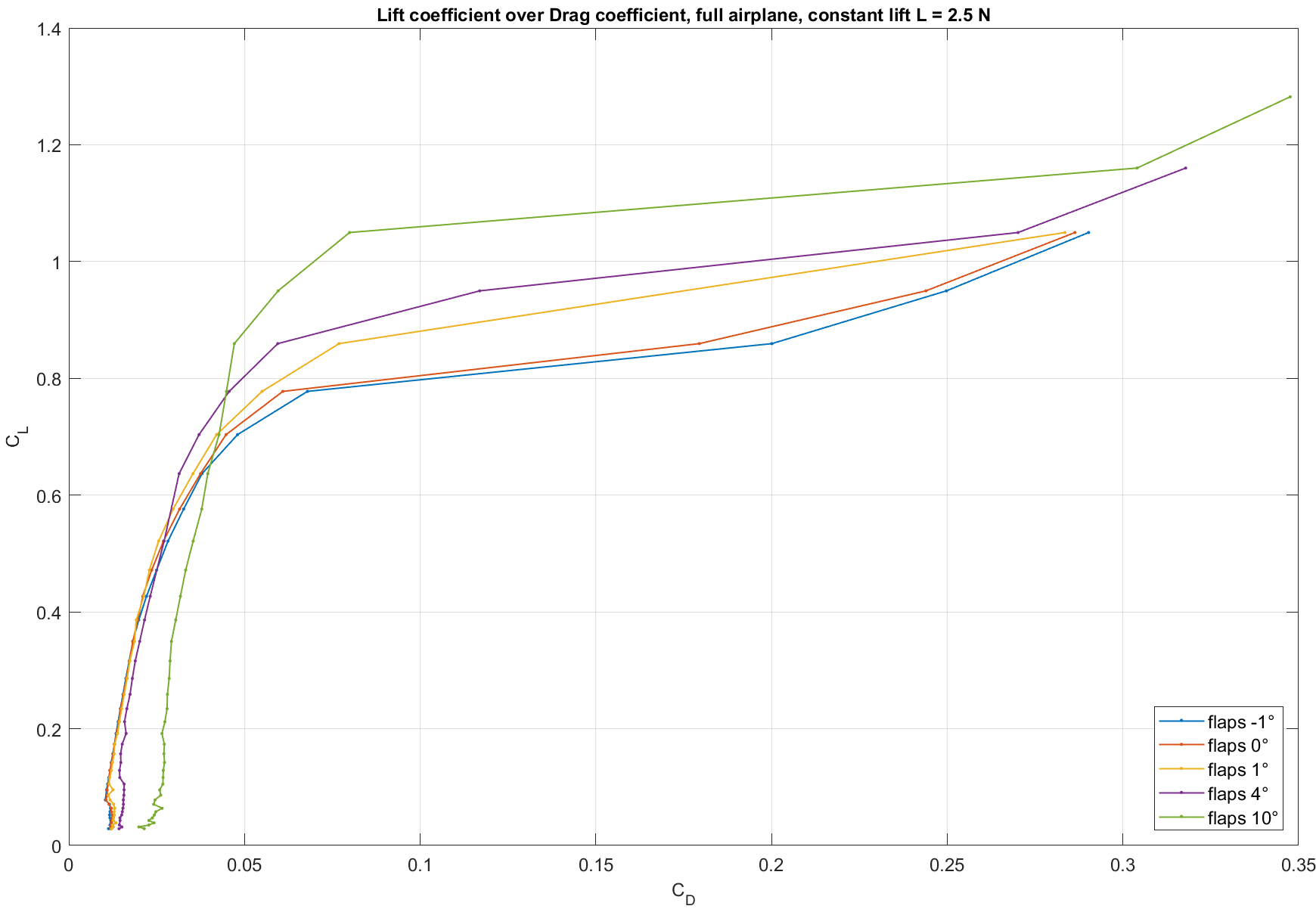
OK, here are some calculated polars for our DLG. I calculated them with my version of tornado vortex in MATLAB. I could have used xflr5 as well, but there are some advantages of tornado:
– the viscous drag is not interpolated from airfoil polars, but calculated directly
– all points in the polars represent a trimmed, stable state of flight. So the elevator deflection is adapted to flight speed. Static margin is set to 9%.
– my version of tornado can handle small airfoil chords (small Re numbers) way better than xflr5.
The polars are airplane polars, so they include elevator and fin. Fuselage drag is not included. I think, for comparison with your projects, a calculation without fuselage drag is more helpful. All polars were calculated for a takeoff mass of about 250g.
You may notice the rather “speedy” design philosophy. We at AkaModell Munich discussed the basic design philosophy in the beginning of the project. Everybody was more in favor of a fast flying, high launching DLG than of a floater. Nevertheless, a possibly large range of good performance was one of the key objectives in aircraft design. One can see, that the 1° flap down configuration posesses an wider peak in the CL/CD to airspeed polar. It was possible to tune the configuration towards more peak performance, but exploiting only one flight state in a theoretic model might turn out far off reality.
Of course, this is theory and calculations only, we are looking forward to see the plane flying in late spring this year!
___________________________________
Hi everybody!
Our project is still going on with full power! In the last weeks, there was a lot of work to do and I had a little less time for writing here. Today I can give an update on our recent progress:
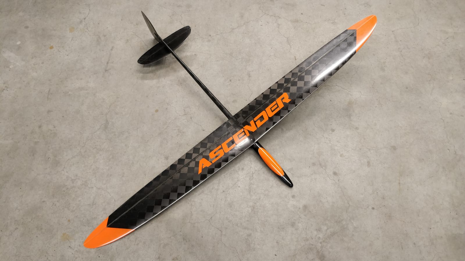
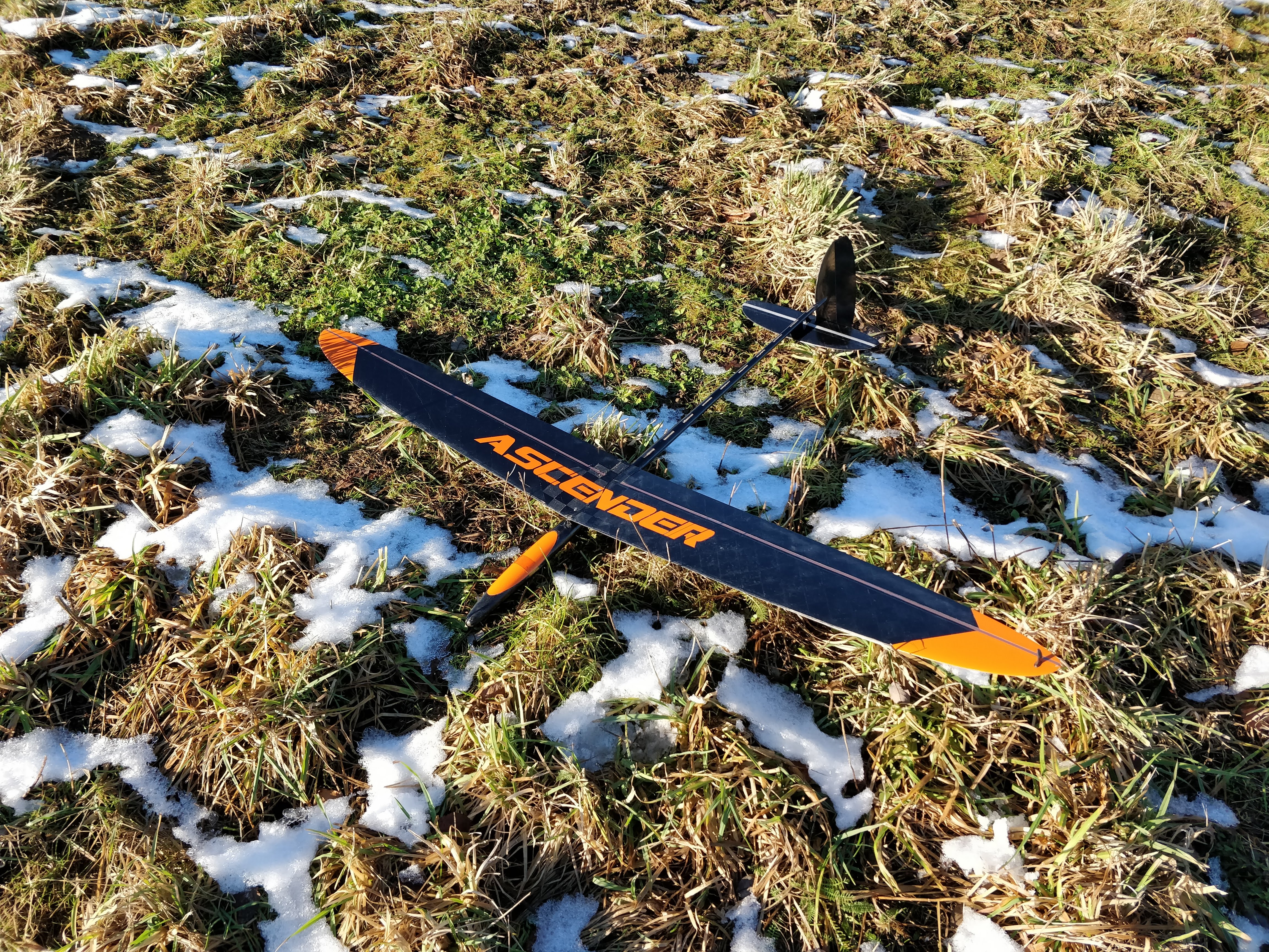
First up we gave a name to the project and the plane. It will be called “Ascender”.
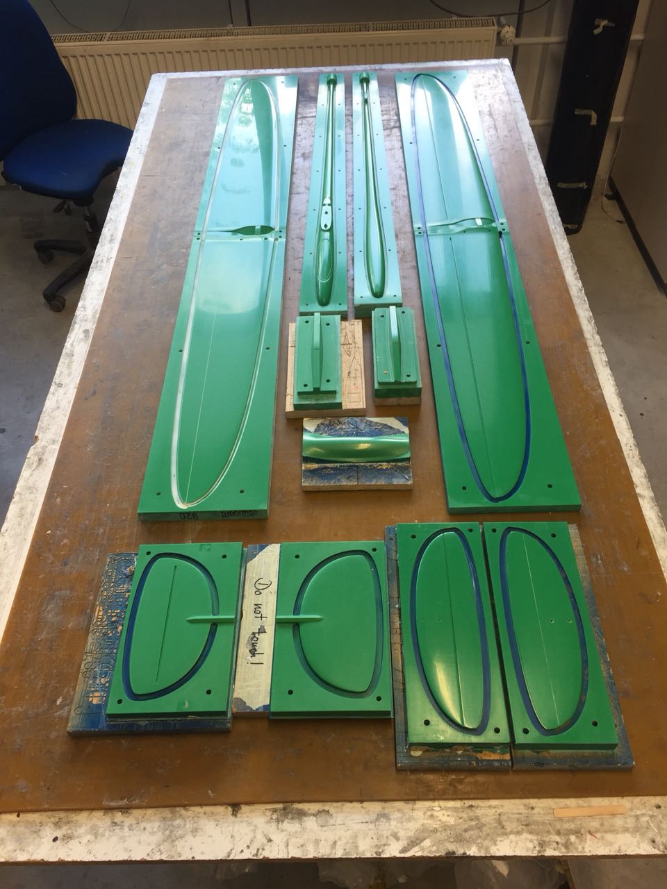
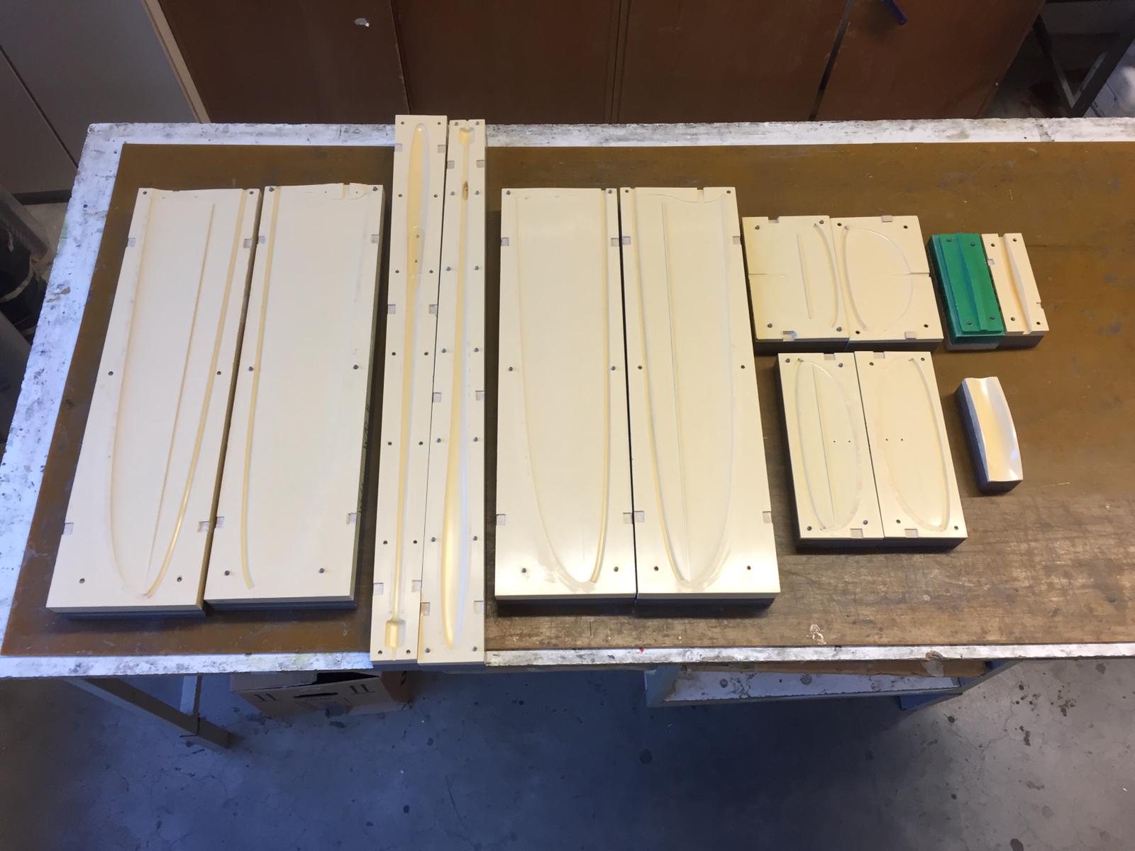
Second, we completed all molds CAD and gave the wing and fuselage mold blocks to a friend nearby who will do us the big favor and mill the four wing and the two fuselage master molds. As far as I know, the next weekend milling of the wing molds will take place. It will take some time to finish the master molds, but my team mates have practiced a lot now!
We also milled the master mold for the fin and small part molds like canopy and wing spar joiner. One of our team members is also working on aluminum molds for the empennage! We are really looking forward to testing aluminum equipment.
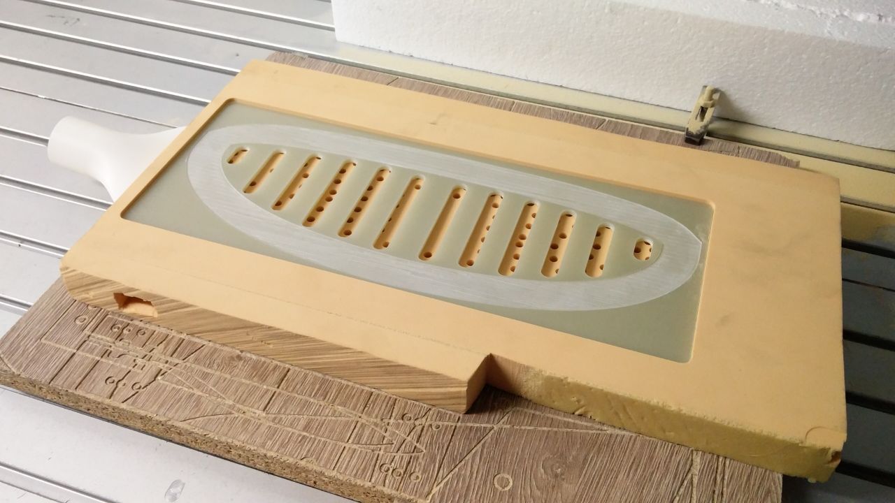
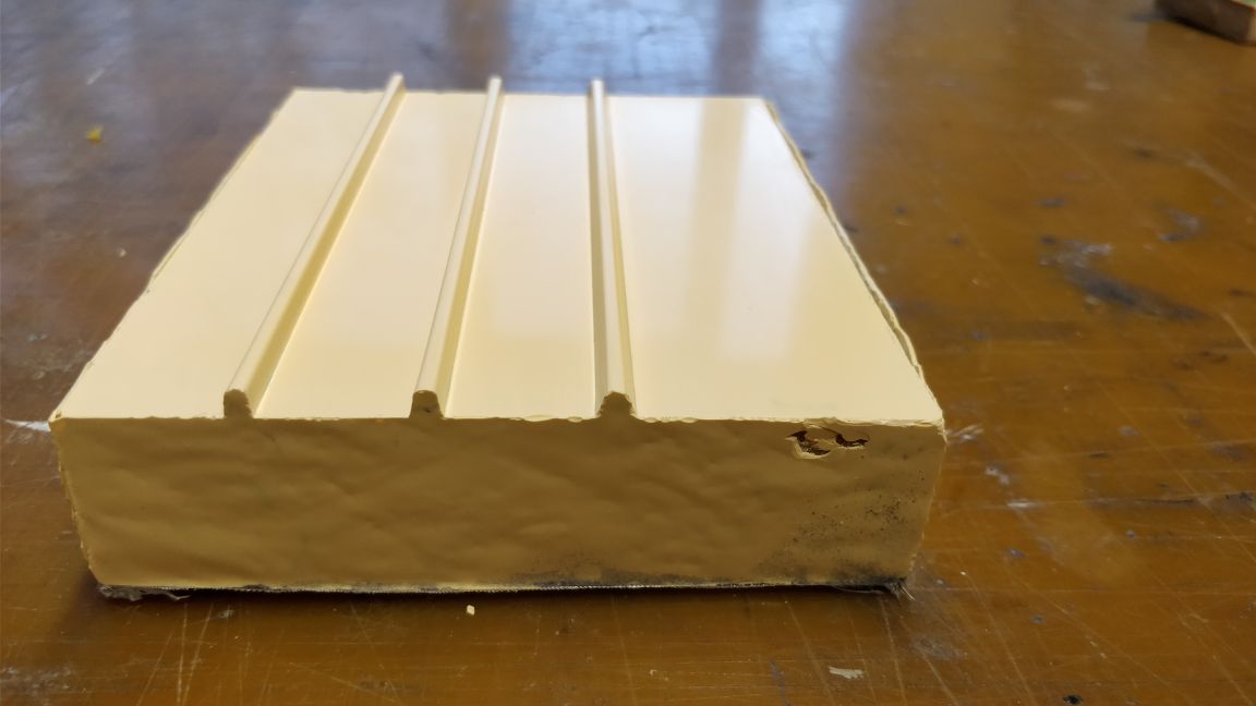
As modern DLG’s feature directly molded flap spars we asked ourselves if it was not possible to build this type of mold also from composite. Usually, these molds featuring such “ribs” for the separation of aileron and wing are made from aluminum. So, we made a test piece with different groves featuring different drafting angles and then we demolded a test piece. Even the groves with only 5° draft angle and with of 2.5 mm came out fine. Nevertheless, we decided to go with 10° draft angle and an approximate 2.5 mm wide grove in the master mold. To avoid bubbles in the edges, we rounded the edges. You can see the geometry of the test piece in the drafting below. We are very happy to be able to build completely by carbon fiber surrounded ailerons in one step.
We also milled the last foam core milling molds. For the wings, it was quite some machining time! It was possible to fit the wing core into a 10 mm thick rohacell board. One board with standard size 1250 x 625 will give us 2 sets of wing cores and 4 sets of tails. Considering the price of rohacell, this is quite an effective use of material. And you get one spare set of tails for the event of damages ?
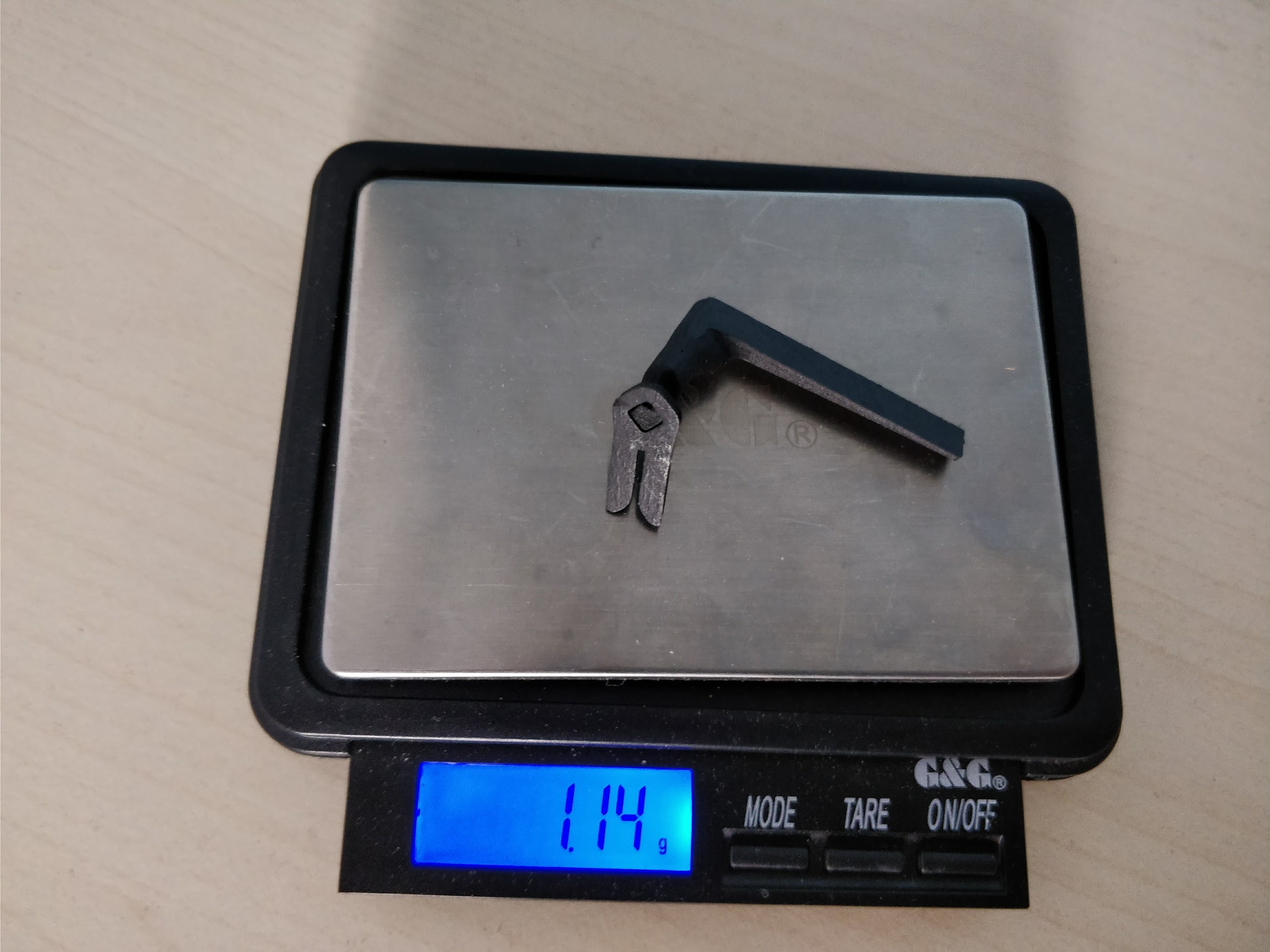
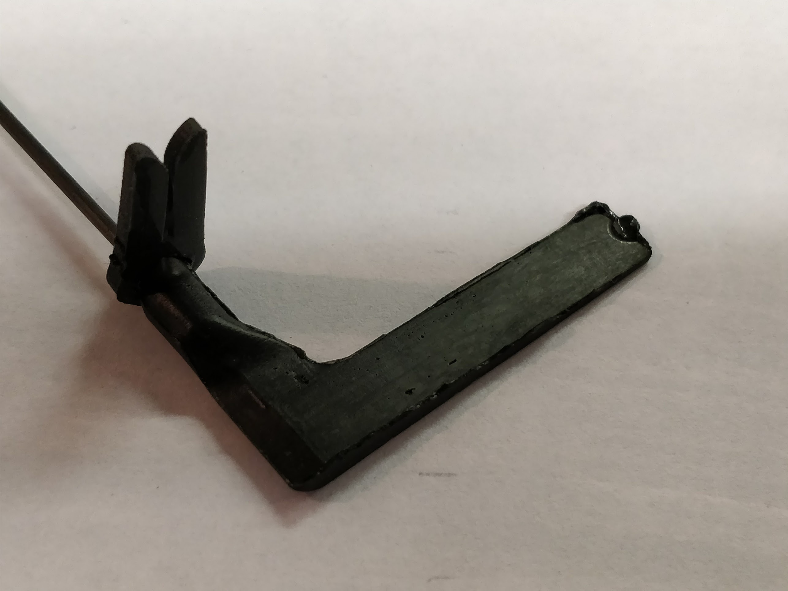
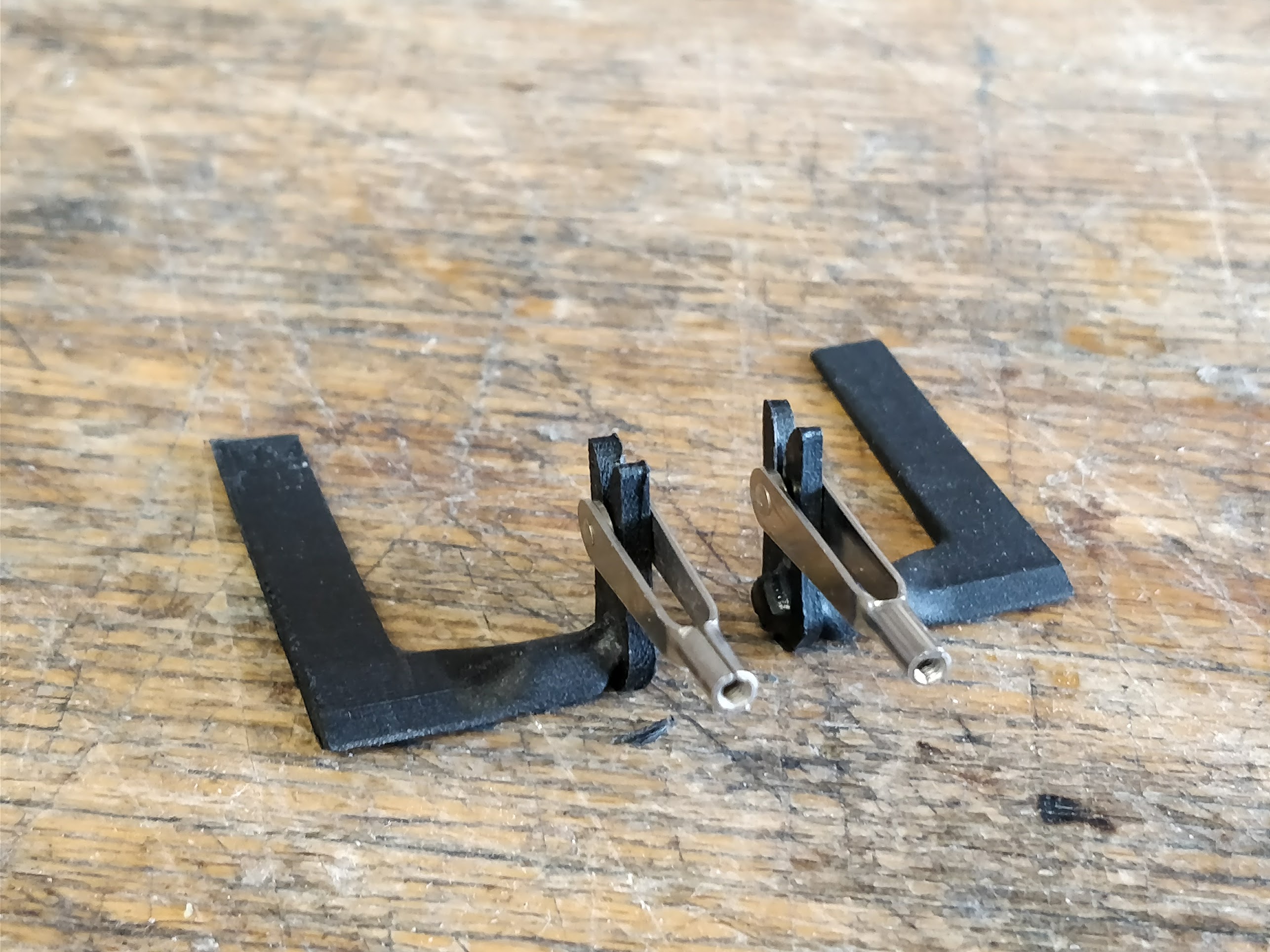
We designed the aileron horn and made some 3d-printed test parts from carbon-fiber reinforced filament. They are really stiff and strong. The possibility of 3d-printed parts is attractive! The parts are printed with 0.03 mm layer height and they have a better quality than the laser sintered parts that I see at my job. However, a molded part is even better. By the way, it is a fork connection system. We liked the idea of having a quick installation of the wing without sacrificing much aerodynamic drag.
We already built a prototype of the fin from 3d-printed ABS molds. It is a great way to get some molded prototypes! We were not sure, if the idea to have a hexagonal insert for the fuselage will work. But it worked out fine. As weight (5,64g) and geometry were pleasant, we moved on and milled the fin mastermolds.
We have built some throwing pegs from a 3d-printed mold. 3d-printing molds is quite easy and I am sure we will keep experimenting with peg geometries. Everybody has a different hand size and different fingers and so we could make quite a range of customized pegs.
Finally, there is great news about further project sponsors! I will make extra posts on this topic to appreciate the support in an adequate way.
I attached a lot of photos from the last weeks. Enjoy!
Best regards, Alex


______________________
There is great progress! We recieved the wing and fuselage master molds today. The set of molds is complete now! There’s still some work to be done, but the team is highly motivated.
We also demolded the second half of the fin production mold and the elevator production molds. They feature groves, which will be ribs in the production molds for seperating the aerodynamic control surfaces. I guess almost everybody in the current F3K scene uses this technique.
Personally, I am really looking forward to building the first fuselages. The “Bachelor” fuselage was really hard to build because of some ugly edges. The “Ascender” fuselage idea is to keep things simple, straight and smooth. And thus hopefully lightweight.
I am really impressed by the videos with sub 200g DLG’s. I don’t know if it will be feasible, but if we can get an Ascender in something under 220g, the airfoil design will begin to really pay off, as the Ascender will still be able to fly at windy conditions and penetrate 😉


_________________________
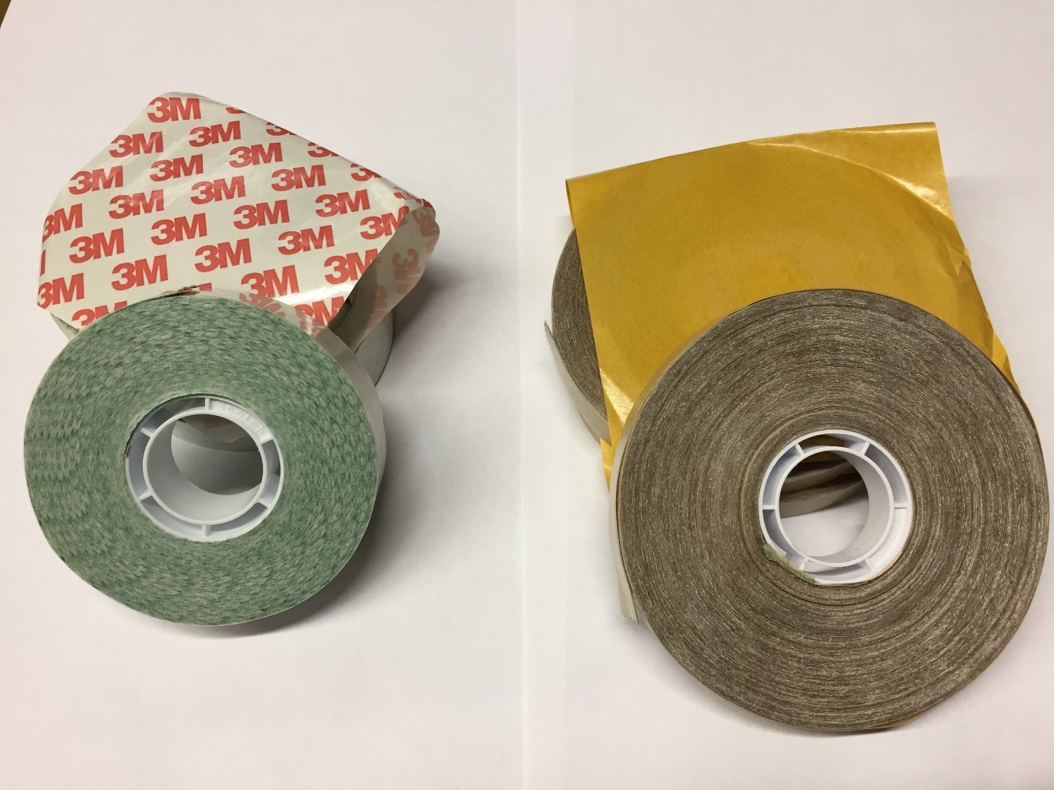
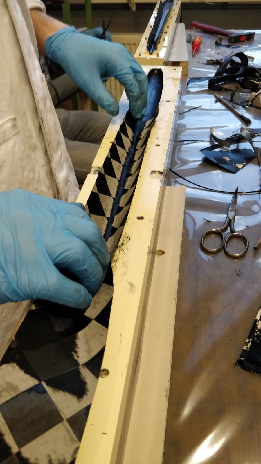
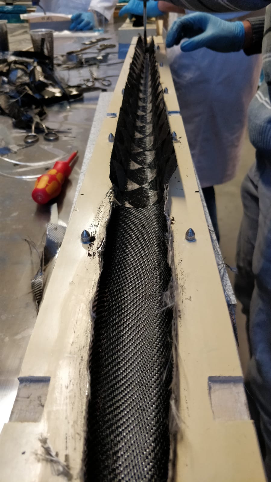
We would like to thank 3M, who supported our project with some transfer tape ATG 926 (12mm) und ATG 924 (19mm).
In the German RCNetwork thread about our project, Jan Henning suggested to use the transfer tape and we are absolutely amazed.
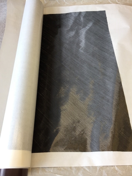
It is perfect for fixing carbon and glass fiber stripes to the leading edge and flap spars. It’s really easy to work with. First we apply the tape onto the carbon fiber fabric, then we cut the material into stripes. These stripes stick well on the foam cores and the fibers can be impregnated with resin then. Nevertheless, the tape is very lightweight.

_____________________
Vladimir Gavrilko was so kind to support us with Carboline 39 g/m^2 and 26 g/m^2. Our master builders say that it’s a pleasure to work with it. Soon, our first “Ascender” wings will be laminated from this material!

_______________________
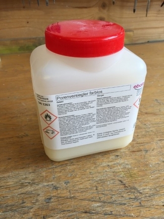
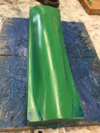
We have been using ebaboard PW920 for many years in different projects, a block material from the German manufacturer Ebalta. It is well suited for milling positive and negative molds with our milling machine. To improve surface quality to perfection, Ebalta supplied us with pore filler for free. The pore filler is applied after rough sanding and it closes the remaining pores in the mold. After 30 minutes drying, the mold can be continued sanding/ polishing. We tested the material already at our canpoy molds, the result can be seen in the attached pictures!
![]()

___________________________
Hi everybody,
We finished all molds to 5000 grain, polished and waxed them. This was very time consuming! Now we are ready for building the production molds.
There were preperations for wing core milling. First wing cores are expected to be milled in June.
Also, we demolded the first production mold of the fin mold with included flap spars. The first fin looks really nice and its weight is again around 5g, but we need some core thickness offset adjustment for the next fins. So far, the production molds from carbon fiber with directly molded rib work absolutely flawless.
As most of the team members are students, they need to take some time for studying too, which slowed the project down a little bit and I was on a business trip to China, but we make constant progress. We are looking forward to having the first full airplane as soon as possible, but we prefer quality work and we will take our time. So please stay tuned and I promise to post news again more frequently!
_____________________________
Hi everybody!
exams for our students and lots of flying in summer steal some time for the project, but there was great progress since my last post!
First, all production molds are finished! So very soon, we will have the first complete Ascender model in our hands.
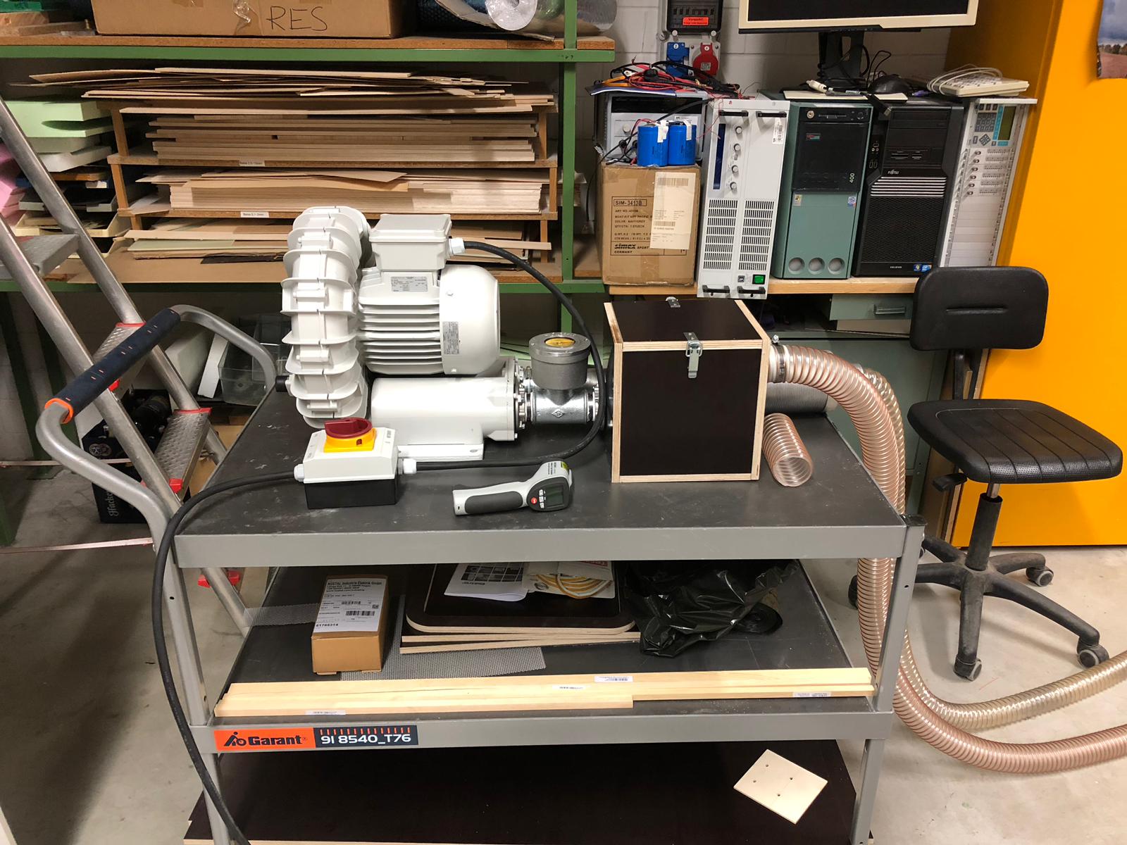
Second, we had a large upgrade in our manufacturing gear and we got a side channel compressor. With this tool, we can ensure an optimal quality of core milling process, without torturing our vacuum cleaners any more.
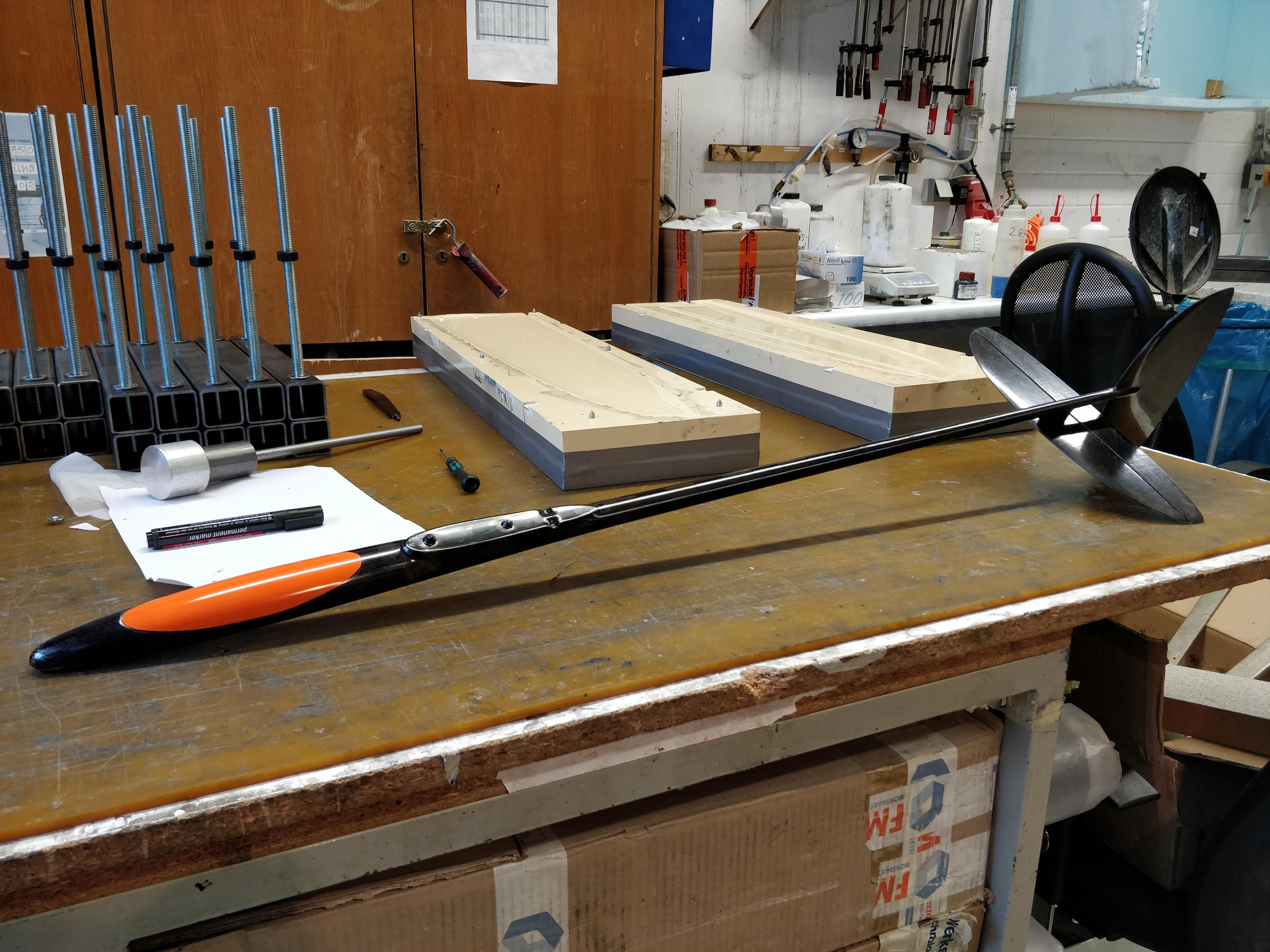
We also built the very first fuselage. As you can tell from the pictures, some edges will need more rovings, but it’s only a matter of experience and training. Including aluminum/steel inserts for screws, the fuselage is at 32g weight. The hexagon ending gives a nice snug fit and the fin is alligned perfectly!
I believe we will have the first full Ascender by end of this year. Coming next: The first set of wings!


______________________________________
Hi everybody!
No big words today, here it is!
https://www.youtube.com/watch?v=CCIiE0W7_Rk
In the next days, we will work out a full flight video and prepare more information for you about our first prototype.
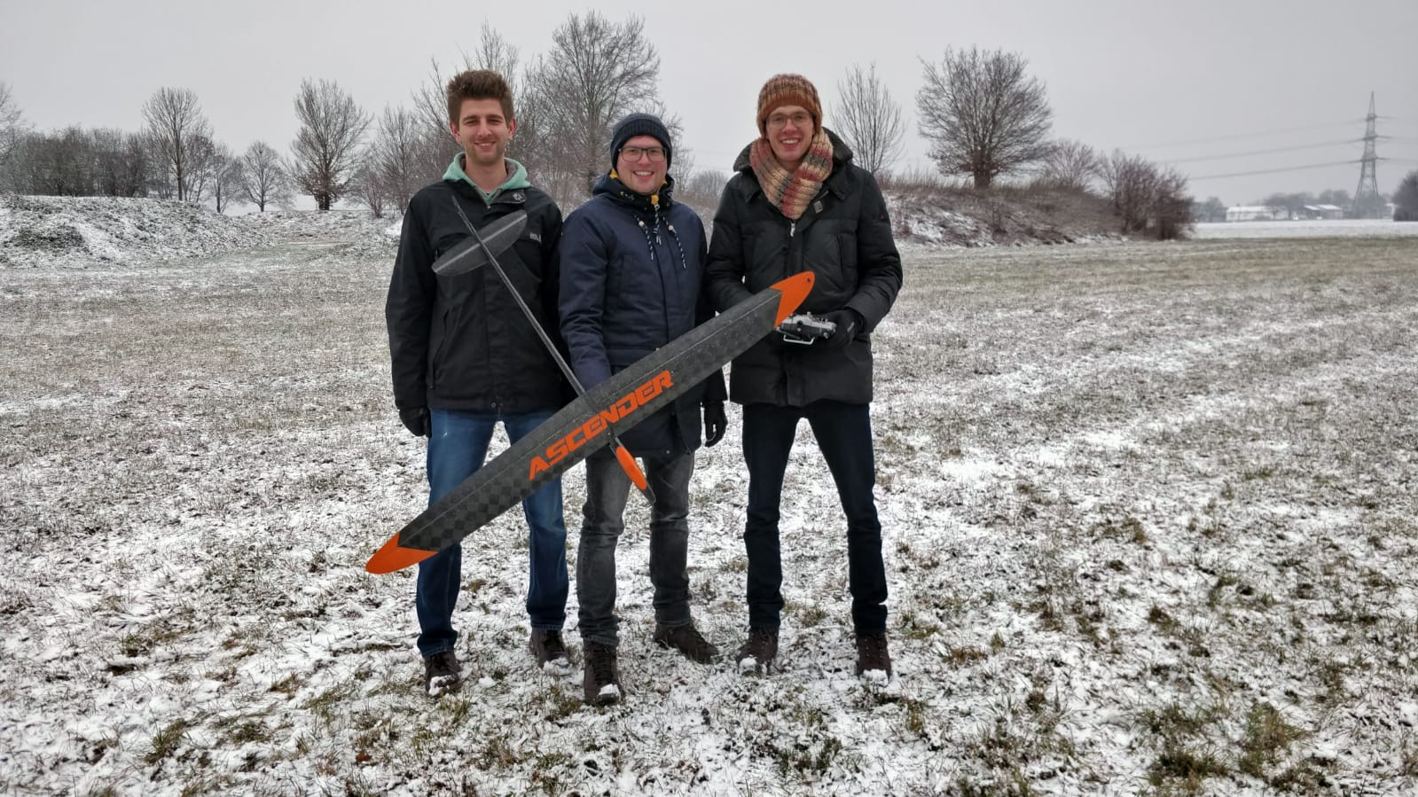
We are really happy about our maiden flight today. It was snowy and we had some icing on the wings, but the Ascender looked really promising in flight!
_______________________________
Today, I had the great pleasure to fly our Ascender Prototype for two hours on my own. I made about 80 launches and the aim was to set up all flight modes, trims and mixers. The weather in southern Germany was very nice today, a lot better than at the maiden last Sunday.
First, I want to give more information about the #1 prototype:
General: For our first plane, we chose a conservative layup. Strong and easy to build, without saving too much resin for getting a nice surface finish. And we wanted to avoid delamination at demolding, so we painted all parts with IMC laqueur.
1) Fuselage
– Thin clear paint film (IMC in-mold).
– Layup: Outer layer 60 g/sqm Aspro Spread tow 0/90 deg. Then 100 g/sqm HM-UD. Inner layer again 60 g/sqm Aspro Spread Tow but +-45 deg. The nose area is three layers 163 g/sqm black stained glass fiber. Small 90 g/sqm patches and UD patches for the elevator pylon. Some 12k rovings in edges.
– Steel nuts M3 for the wing, aluminum nuts M3 in the pylon.
– Fuselage weight: 34g
2) Tails
– Thin clear paint film (IMC in-mold).
– Layup: Outer layer 16 g/sqm GRM Carboweave. Spar A-spread tape 30 g/sqm. Leading edge GRM Carboweave 20 g/sqm on 3M transfer tape . Patches from 20 g/sqm GRM carboweave. Kevlar hinge from pre-laminated 65 g/sqm fabric. 6k rovings in the leading edge. Trailing edge black microballons resin. Carbon sleeve for the hexagonal insert of the fin.
– Fin weight: 7 g
– Elevator weight: 6.5 g
Yes, the tails came out a little heavy. We will improve!
3) The joiner is built seperately from carbon sleeve and rovings (24k M40J). The Rohacell core is machined by CNC.
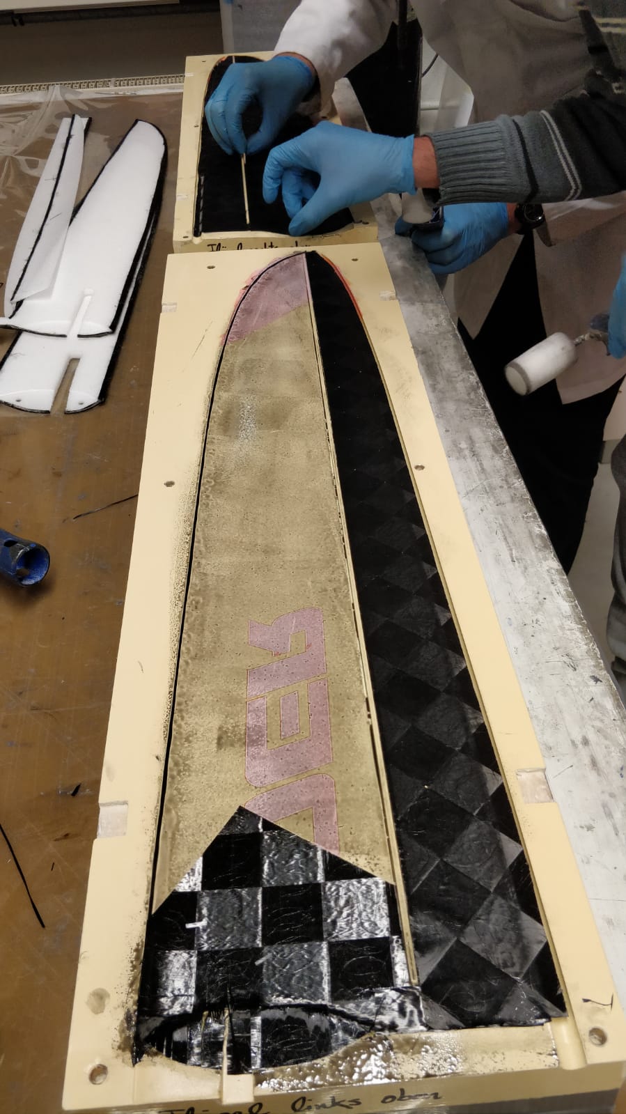
4) Wing
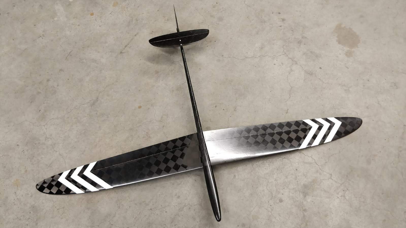
– Thin clear paint film (IMC in-mold). Decals with orange and white IMC.
– Layup: Outer layer 62 g/sqm Textreme IMS. Also some reinforcements same material. Spar caps from overall 18k to 6k M40J rovings. Joiner pocket Kevlar sleeve. Leading edge 40 g/sqm GRM Carboweave on 3M transfer tape. Flap spars also from 40 g/sqm Carboweave. Some 3k rovings for edges.
– Wing weight (including joiner, peg, aileron horns) 131 g
We did without wing spar to reduce complexity of the building process and to avoid optical footprint of the spar. Maybe, we will try the next wing featuring a spar and UD tape for the spar caps.
5) Servo installation
– The servo mount is 3d printed. It weighs about 6g. It holds 4x KST X08 Servos and there is some space for a 10 mm brass bar as ballast. The servo mount is then screwed into the fuselage, it is just fixed from below and the screws run through the fuselage wall. Quite pragmatic, but really practical, because the servo mount still needs some improvements.
– I will make an extra post on the servo installation soon. Once we have the final servo mount 😉
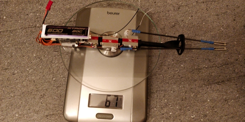
6) Other components: We wanted to use a 1s 600 mAh battery, but for the first flights I used 2s 350 mAh Lipos. My reciever is an 8 channel with integrated vario.
Due to the slightly heavy tails, we needed about 12g lead to balance the plane. Now, its AUW is 269 g. Not perfect yet, but we did not try to save resin. With some slight changes we should not need much lead for balance and also less than 250 g AUW appears realistic.
Nevertheless, the 269g prototype flies really nice. All doubts, wether the thin airfoil choice would produce delicate flight behavior could not be confirmed so far. But it’s true, the Ascender is not the floater kind of plane, it flies really fast when you set the speed flightmode. Another indicator for Ascender’s high speed quality are the launch altitudes. I can’t tell launch altitudes right now, because I am a really bad launcher. But I cracked my personal launch record so far with the Ascender today with ease! Some other guys in the team do a lot better. And we will meet up some F3K contest pilots soon and then we will see! Rudder works like a charm on this plane, it is so sensitive to slight control inputs.
In January, we will build the next prototype of the Ascender with slight improvements. We are open to your comments and recommondations. We believe, there is still a lot of potential. And thank you everybody for the positive feedback so far!
If somebody wants to meet us and the plane, we can get into touch!

_________________________________
Hi everybody!
Today, I have three new things for you:
1) Another Ascender flight video
https://www.youtube.com/watch?v=_A28XtNgVuU
We are still working on a nice full flight video, so stay tuned.
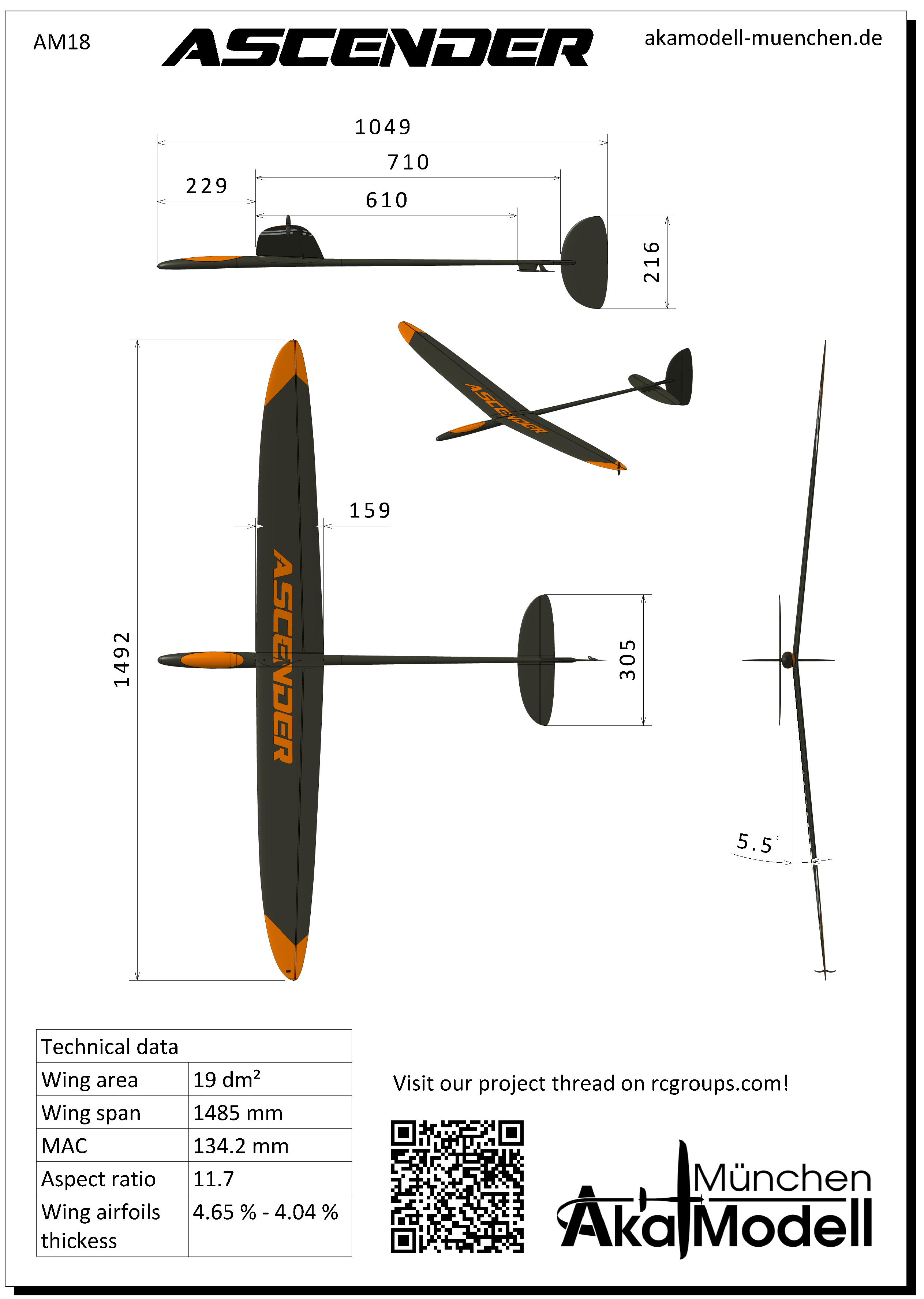
2) A data sheet of the airplane. Somehow, it is a must-have.
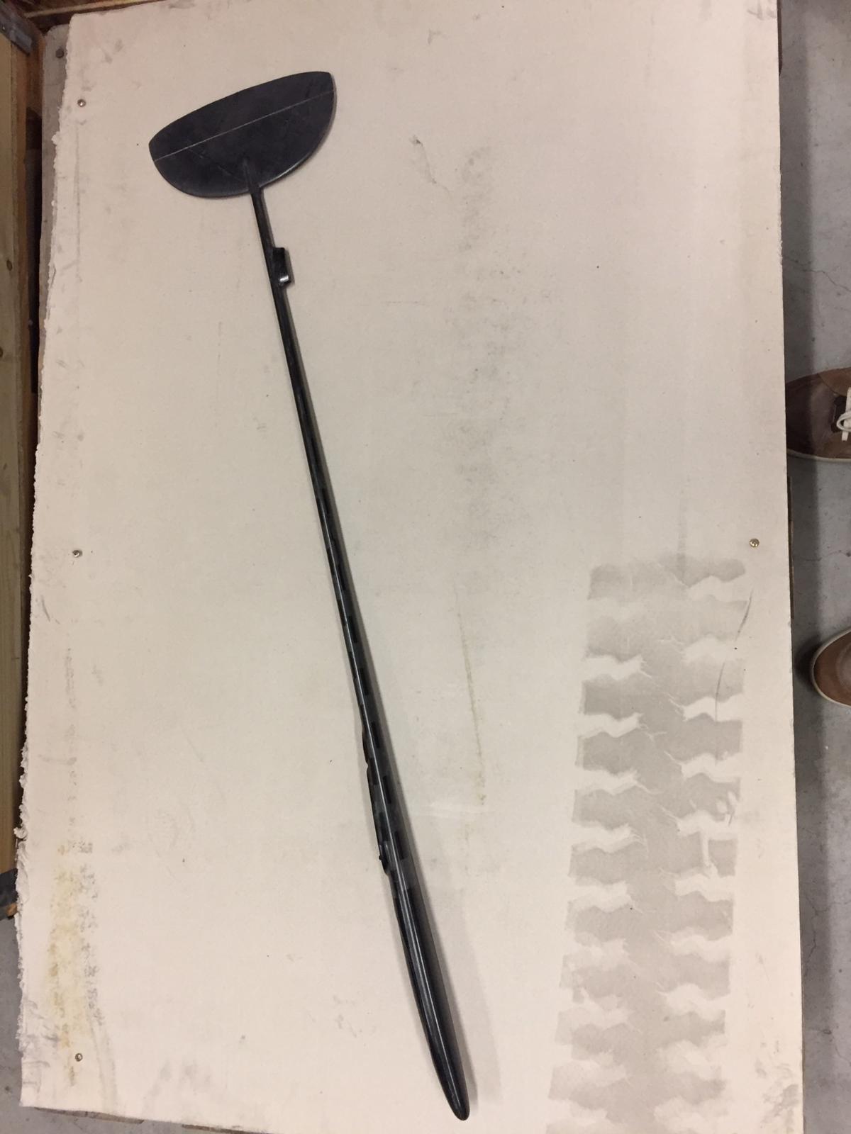
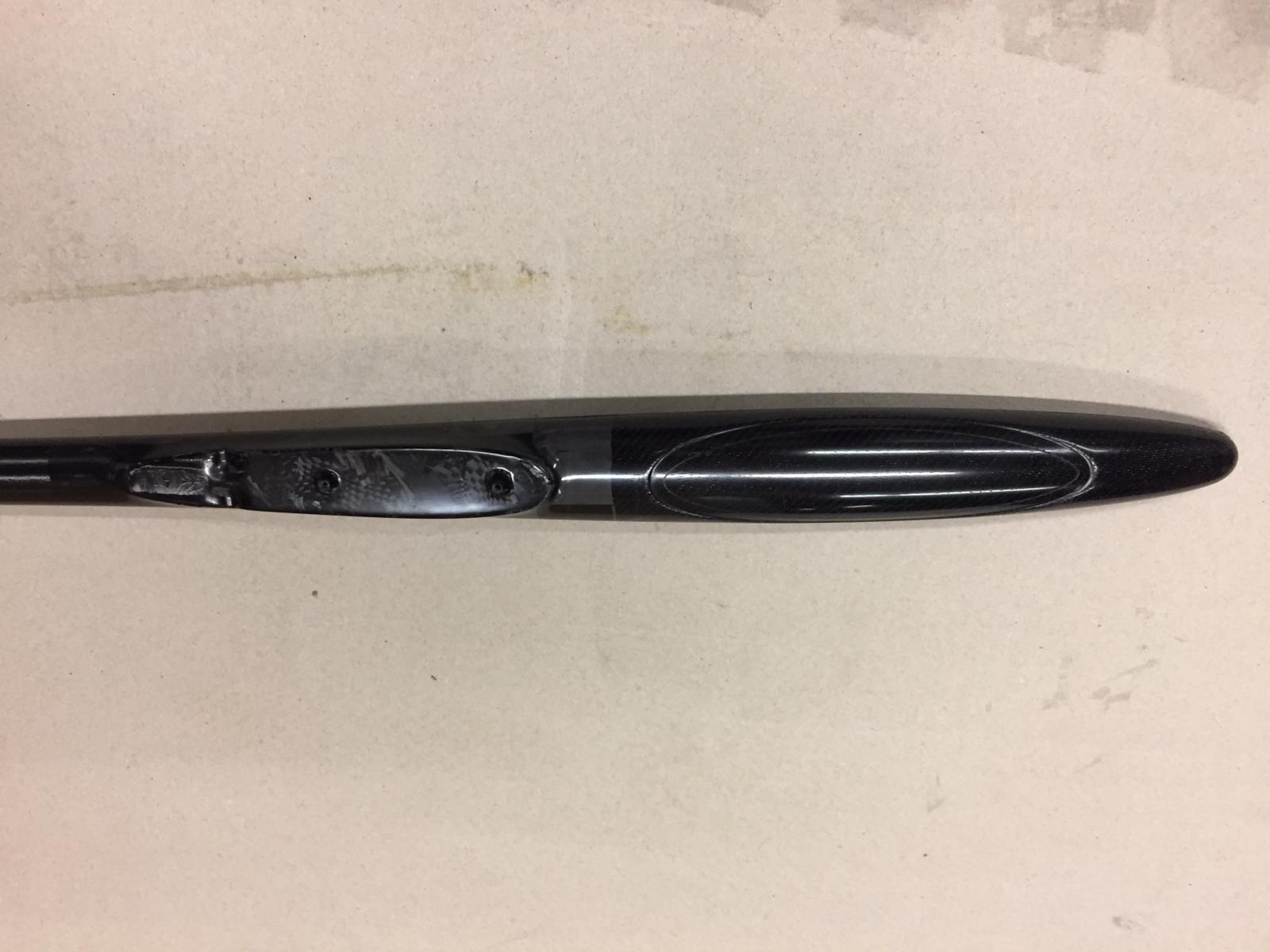
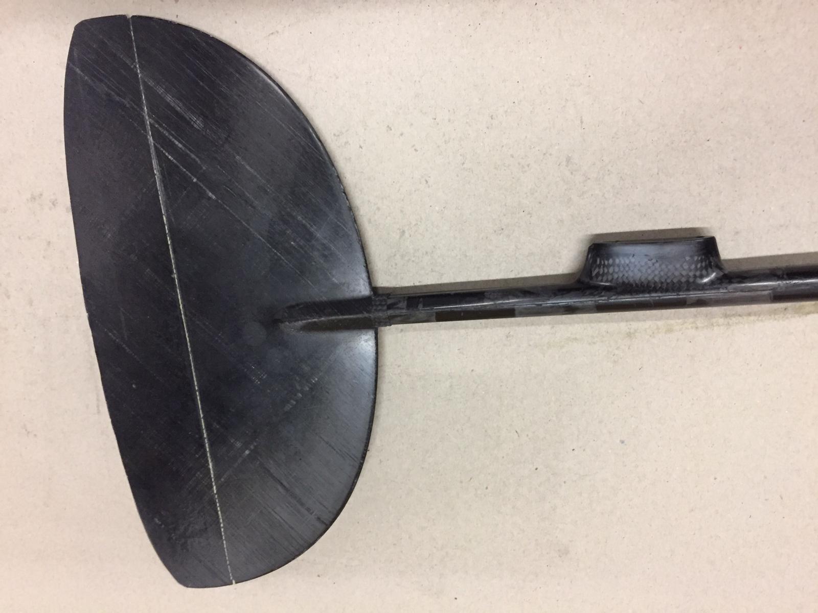
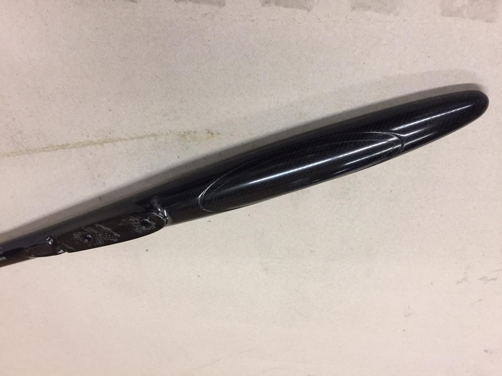
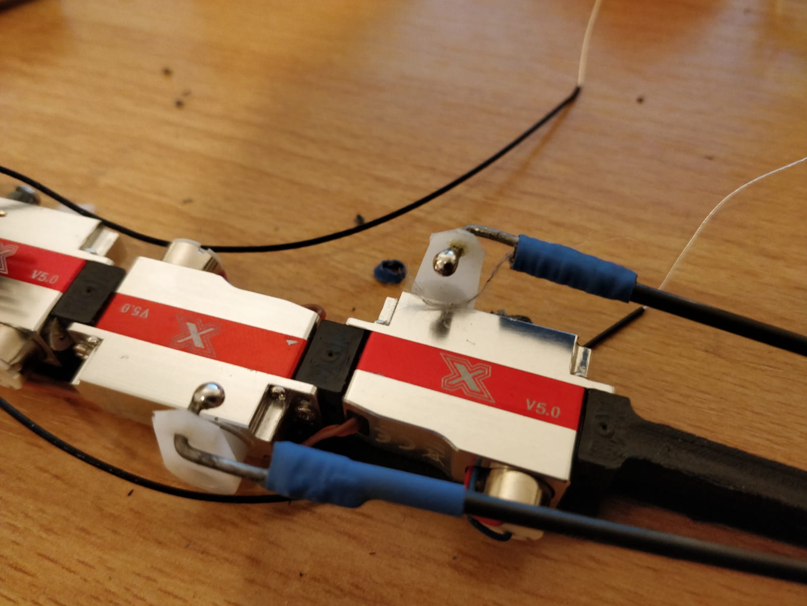
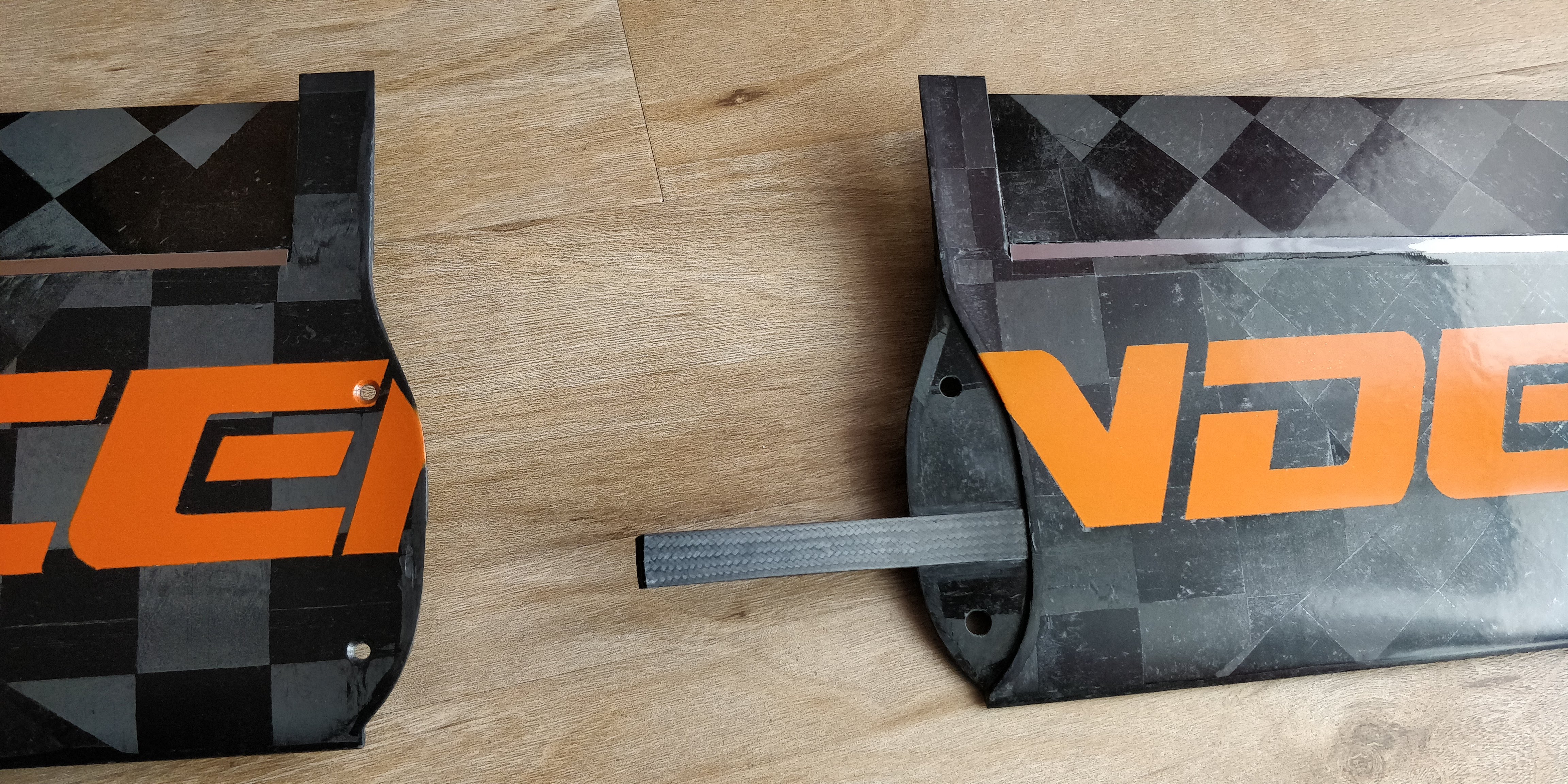
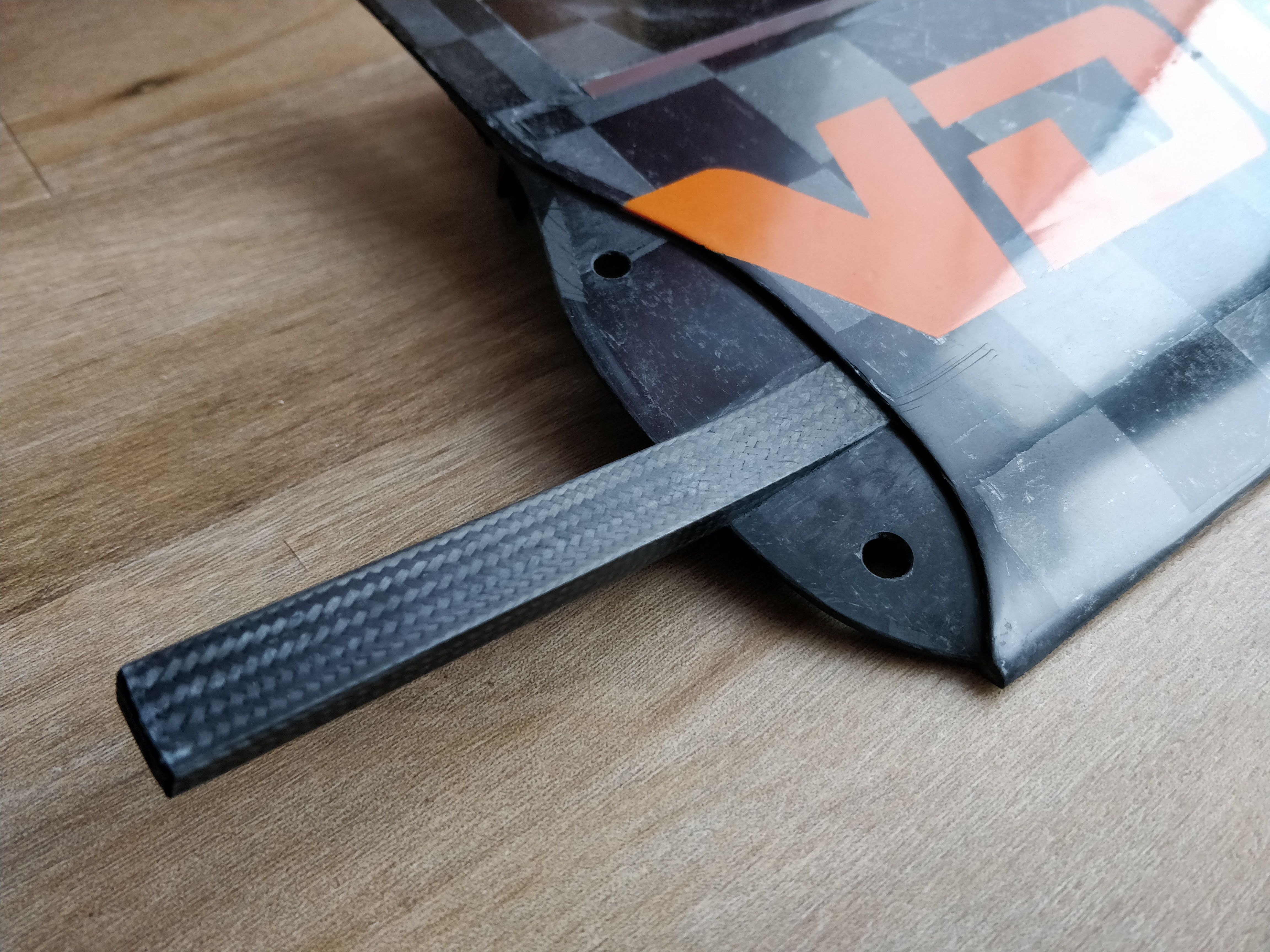
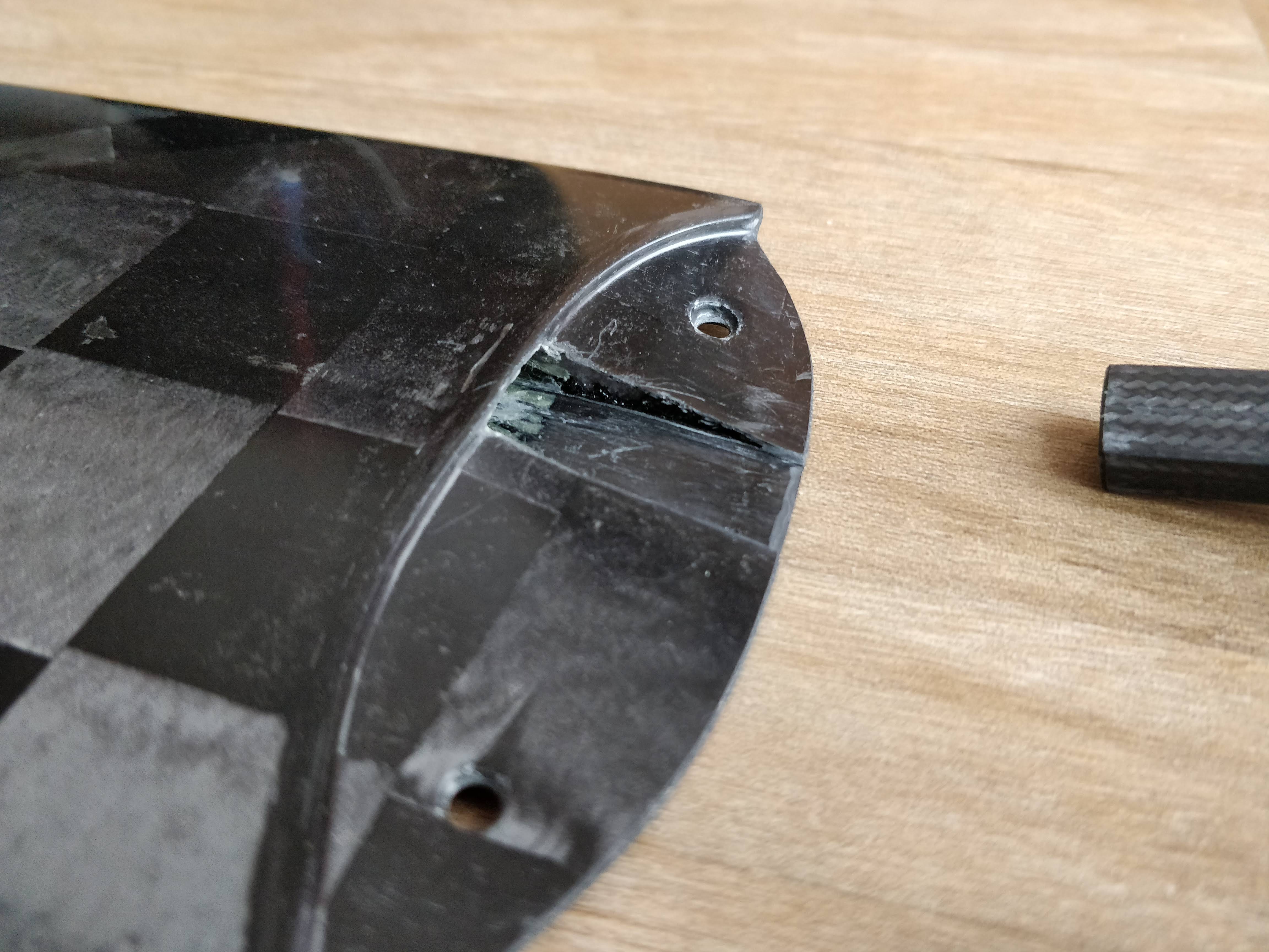
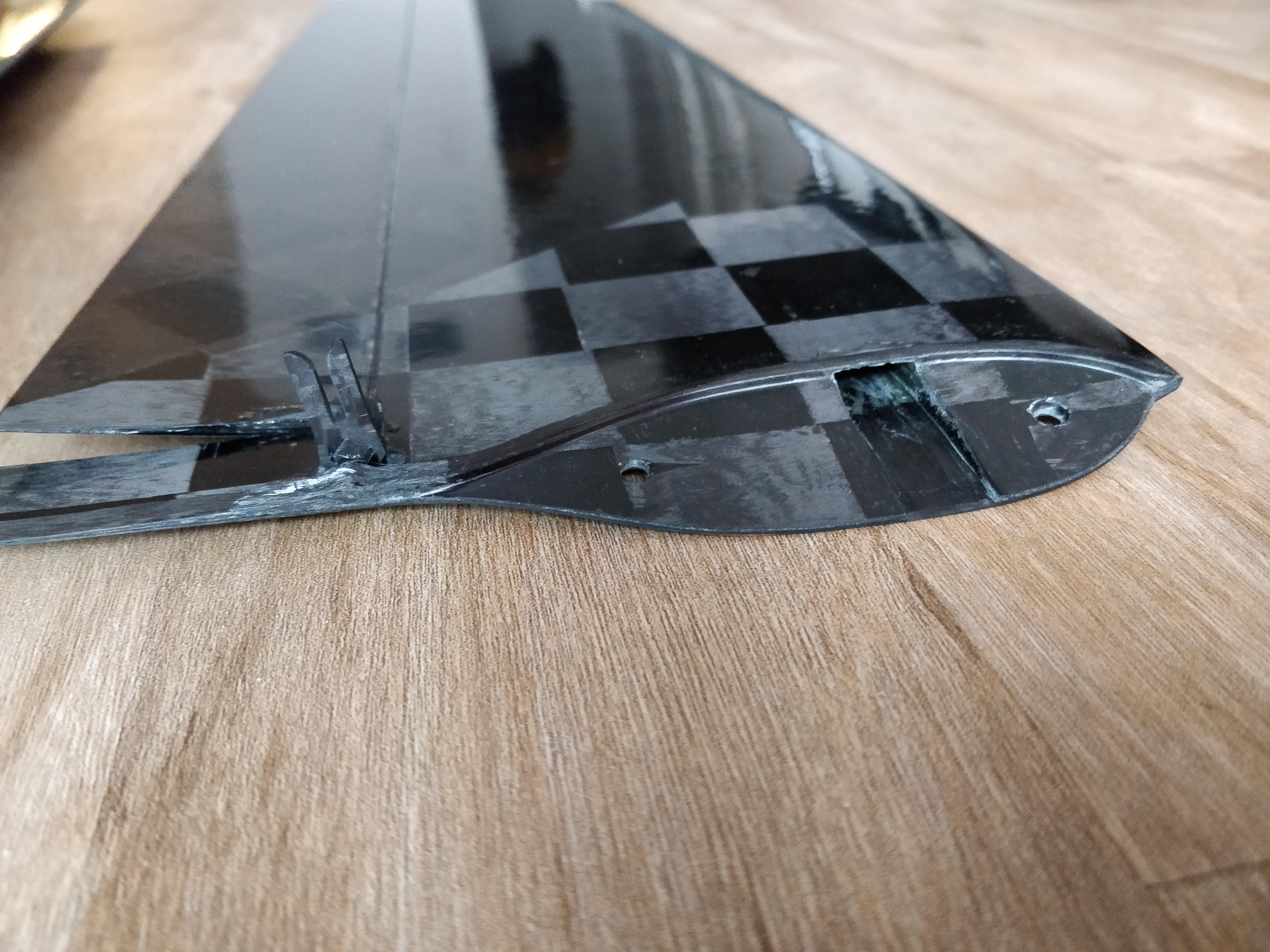
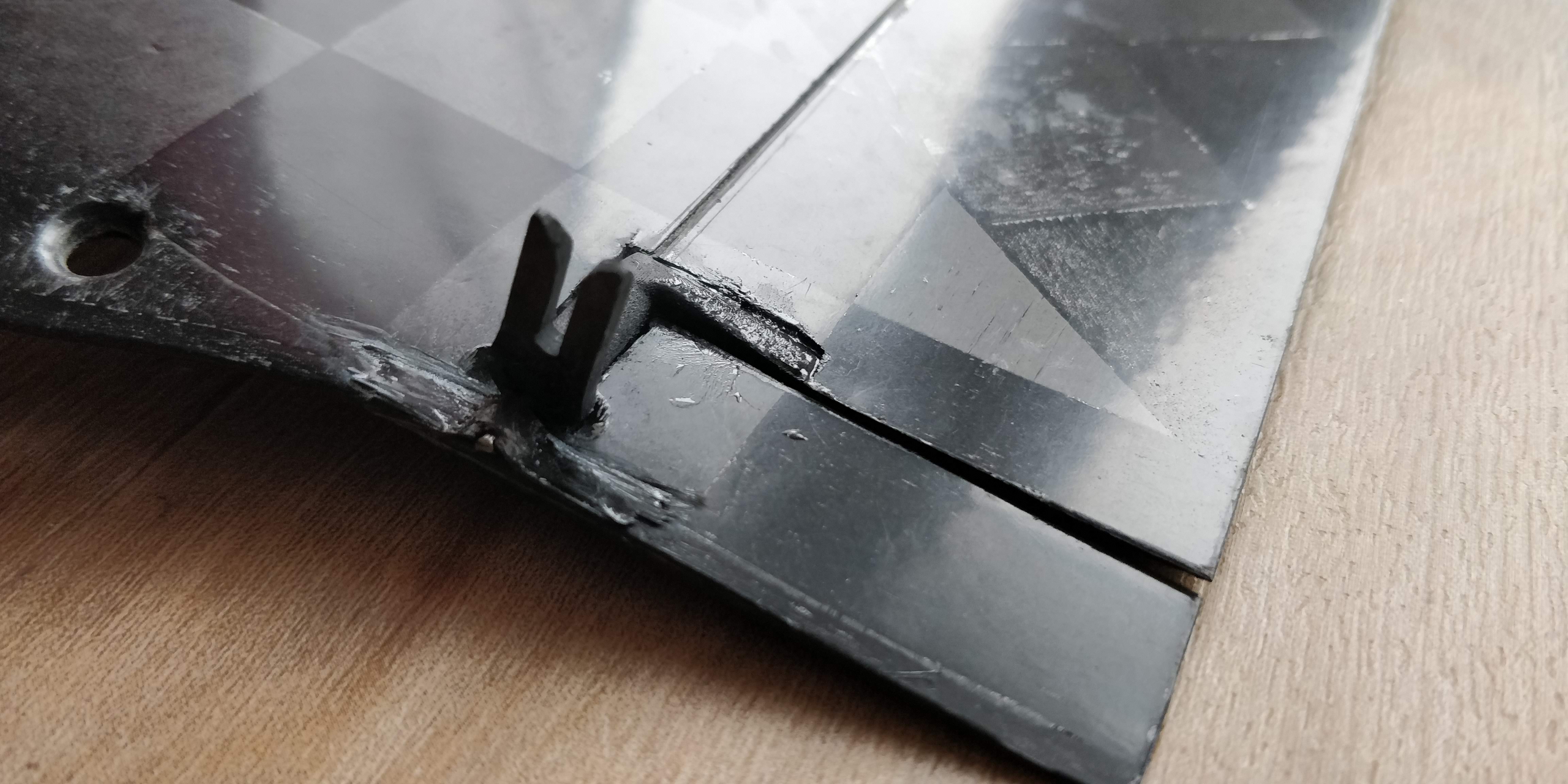
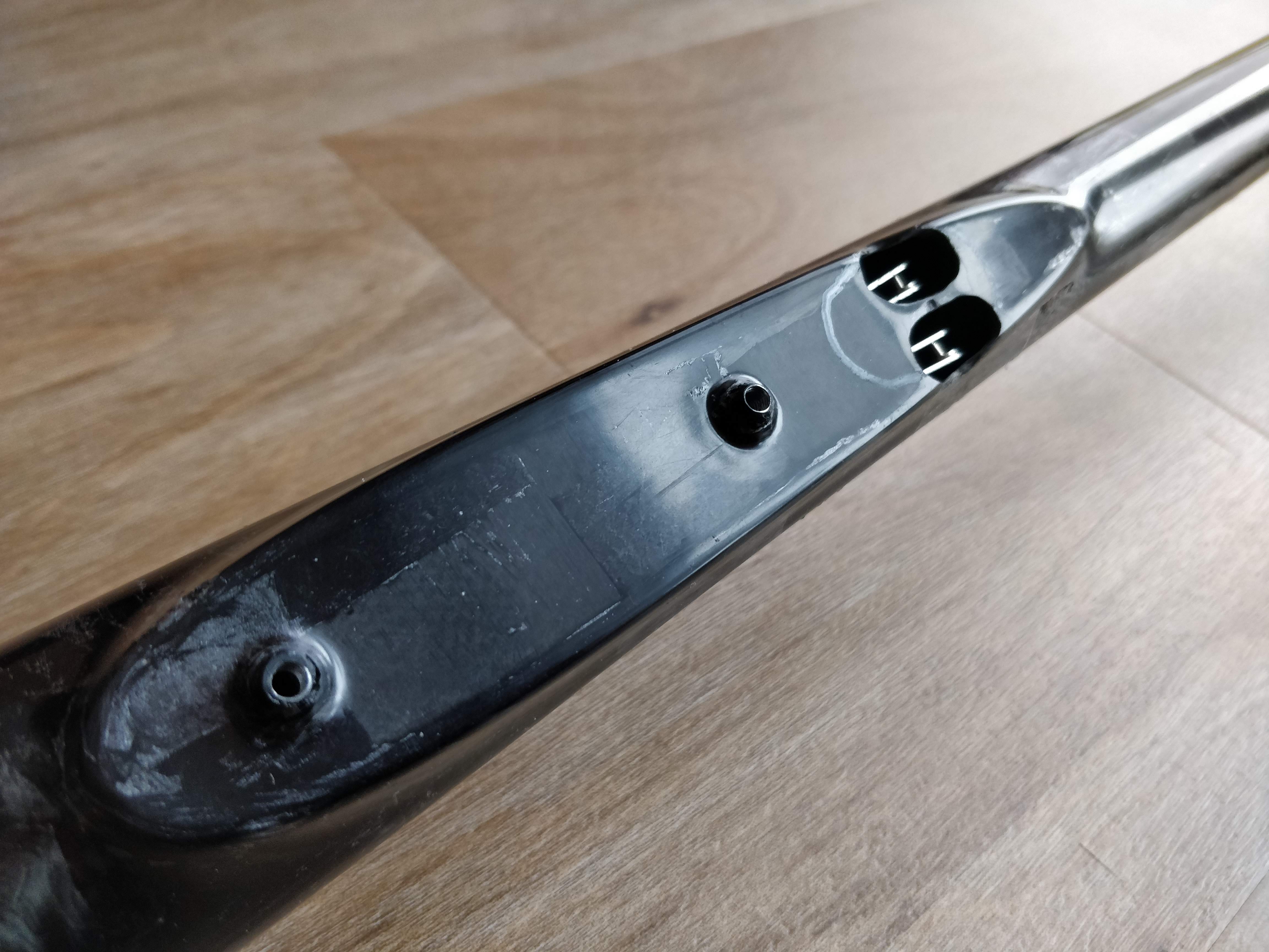
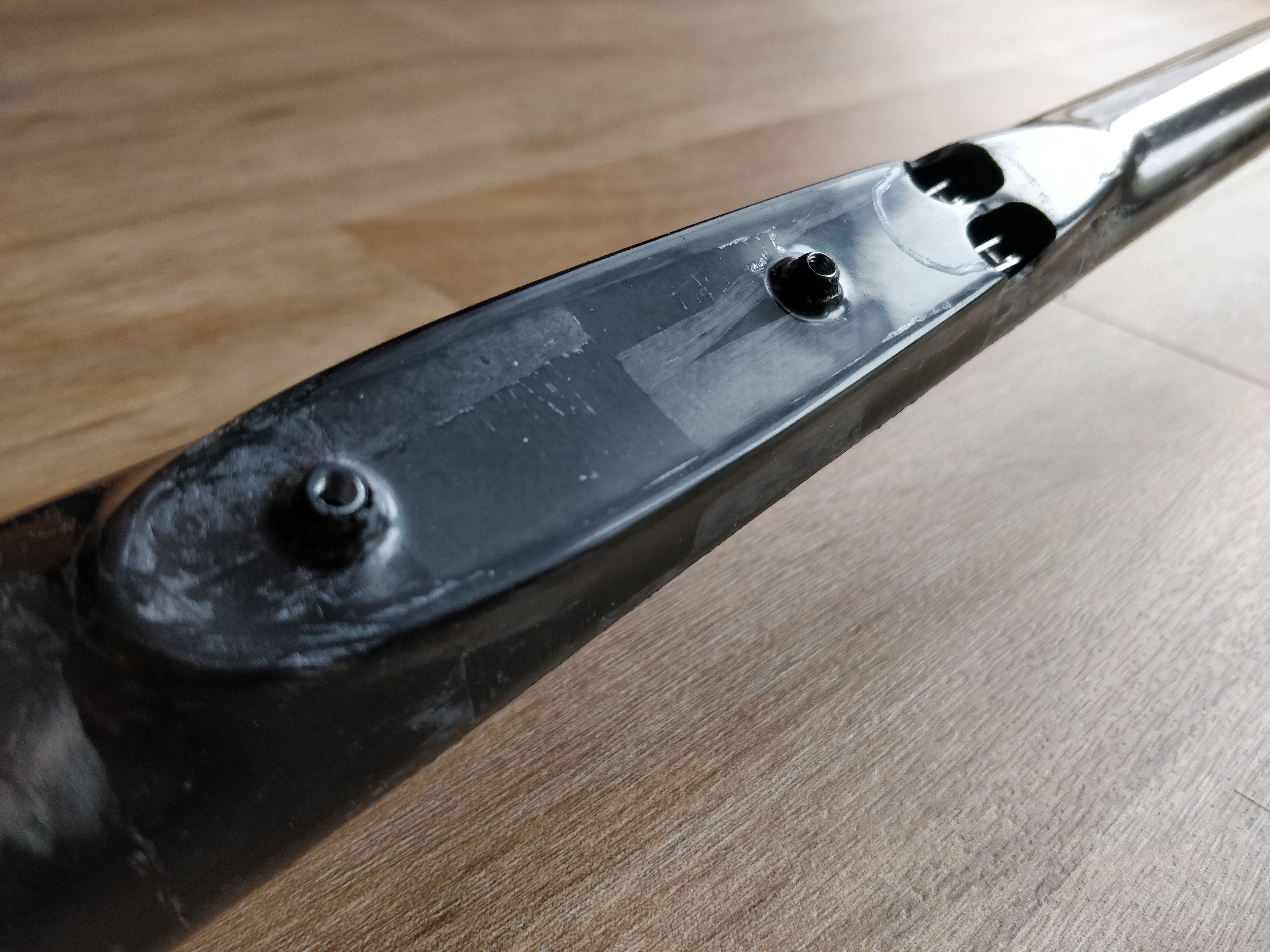
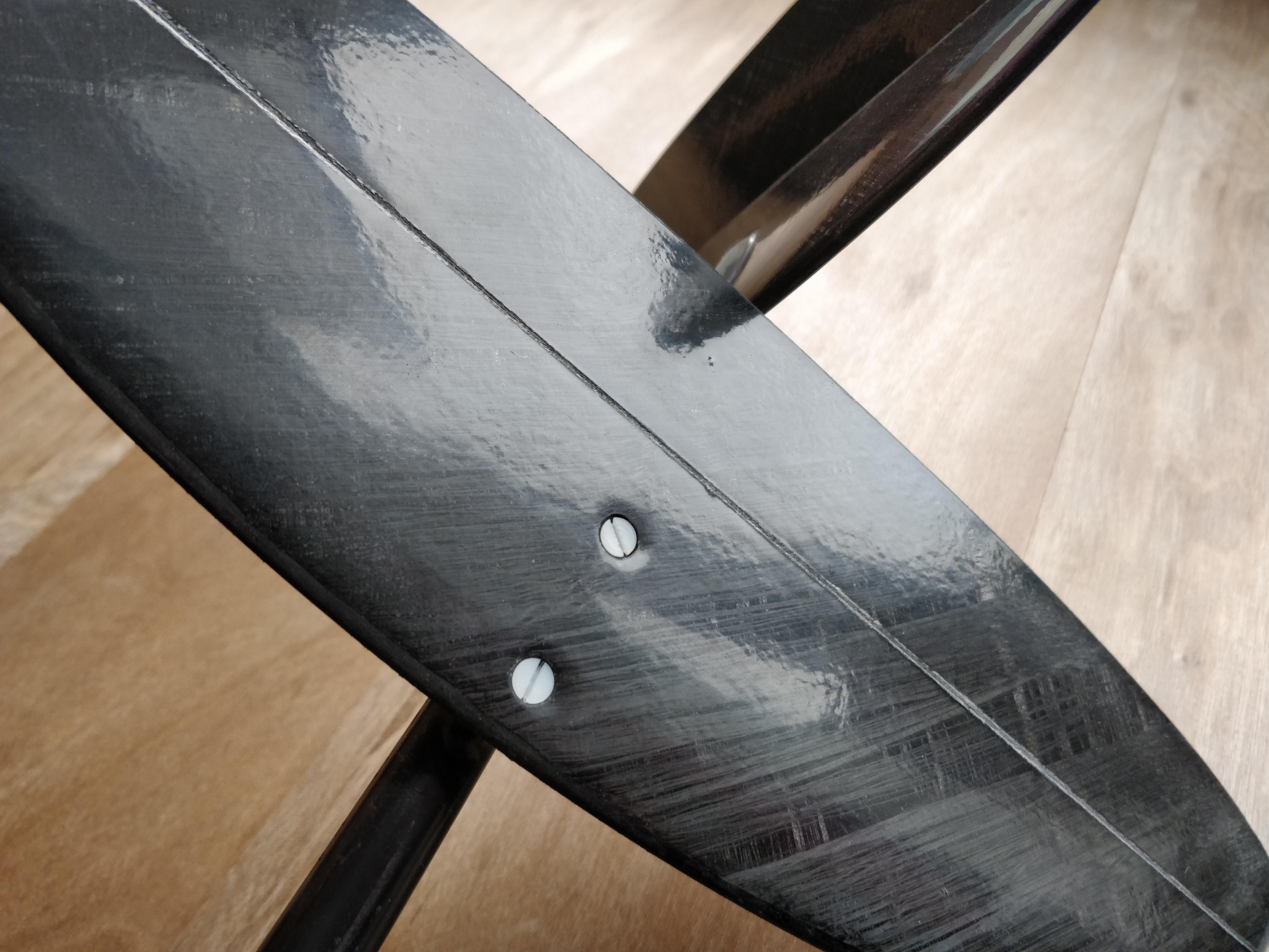
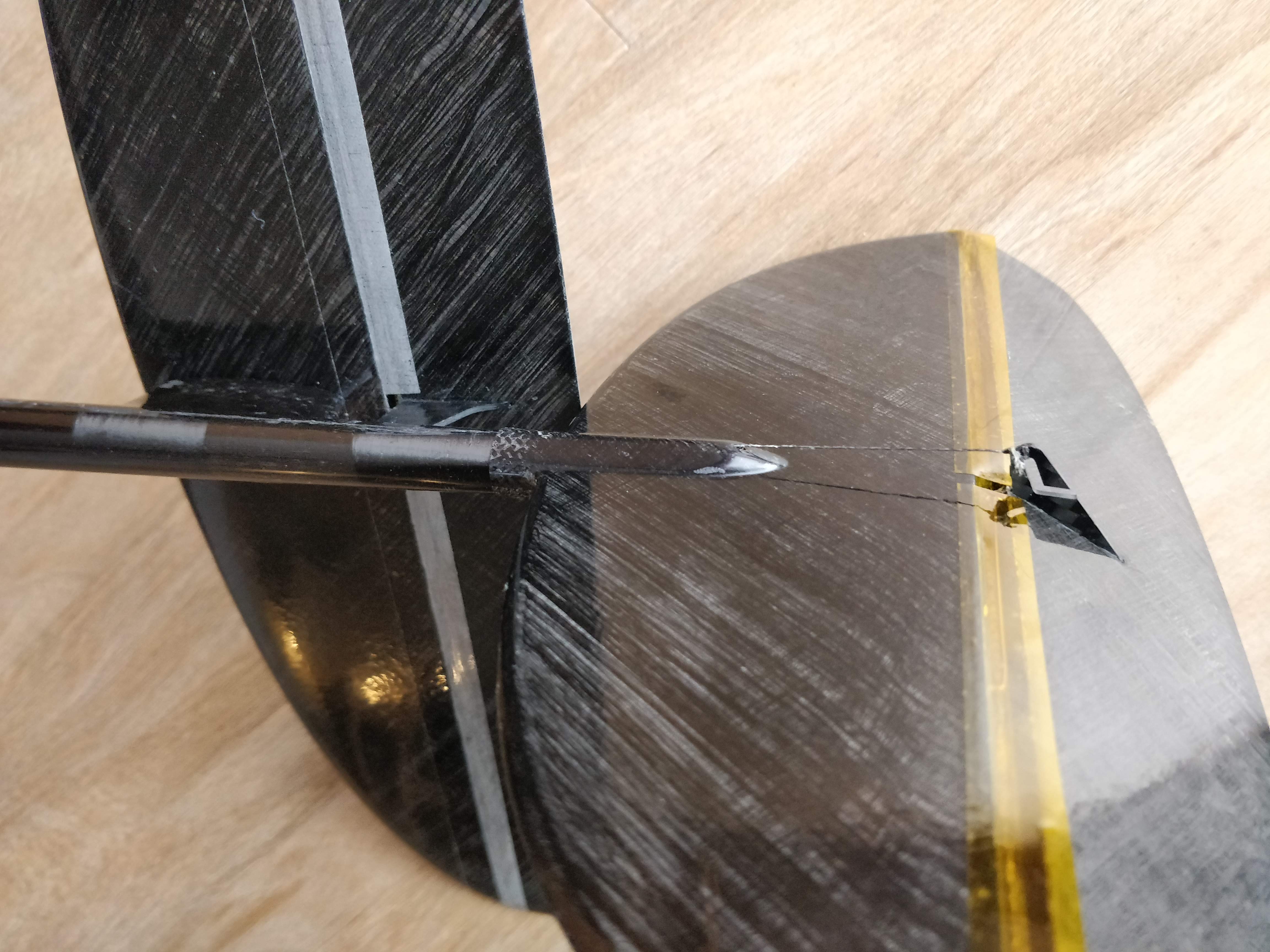
3) Some detail photos of the unique Ascender wing root area. The joiner is glued in the left wing at molds closing. I attached also some pics of the aileron connection to the servos in the fuselage and detail photos of the tails.


_______________________________
https://www.youtube.com/watch?v=BfKPaVpJLHk
_______________________________
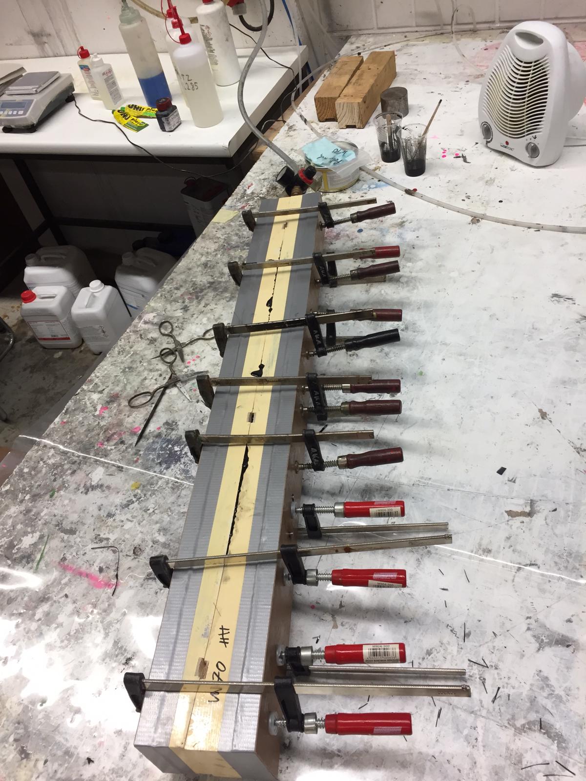
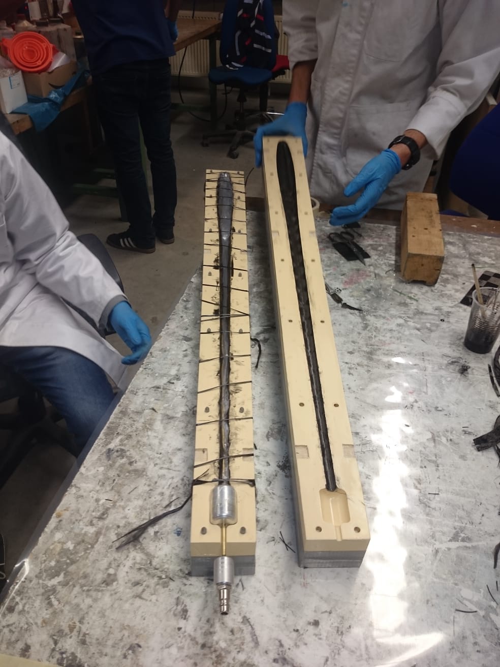
Yesterday, we had a marathon-like 12 hour building session. We painted, prepared all fabric and laminated all parts of prototype #2. The day before, we CNC-milled all Rohacell cores and laminated a spar joiner.
Prototype #2 features:
- tails: 16 g/sqm Carboweave (GRM)
- fuselage: 62 g/sqm Aspro A-60 IMS 0/90°, 100 g/sqm HM-UD, 62 g/sqm A-Spread IMS
- wing: 40 g/sqm Carboweave (Vladimir’s model) for the wing and 62 g/sqm A-Spread for the ailerons. There is a C-type spar now in the wing core. Spar caps are made out of stripes 100 g/sqm HM-UD. Some reinforcement patches 62 g/sqm A-Spread.
With this layup, we hope to get a stiffer but lighter wing. As the airfoil is quite thin, ailerons are still in strong layup.
Hardening and tempering takes some days, we are looking forward to the results.
We used a lot of sponsored material for this plane again! Thanks to GRM, Vladimir Gavrilko, Evonik, 3M and Asprotec!
We already got some purchasing inquiries for the Ascender. Very sorry, but selling the Ascender on a regular basis is not planned and intended. It is so much work to build one! This project is still hobby for us (sometimes very demanding). But a sucessor like an “Ascender 2” might be possible in case Ascender (1) gets positive feedback by contest pilots and some other factors come together. First, let’s have some fun with the current non-commercial project!
Again, thanks for your comments here and the german thread on rc-network and facebook groups. We appreciate the F3K-community a lot! I’m sure, it will be possible to see the Ascender live one some contests in Germany in 2019.